Just added: a new template for inline tube adapters!
New on iteration3d: create your own inline tube adapters!
Generate on demand custom connectors between two tubes of different diameters, perfectly aligned… or deliberately offset.
Set the lengths, diameters, and thicknesses of each tube, adjust the transition between them, apply an optional axis offset, and add fillets to the ends to ease insertion.
Thanks to a robust modeling process, transitions are optimized and fillets are automatically adapted to the geometry.
A custom connector, ready to print, in just a few clicks!
What is an inline tube adapter?
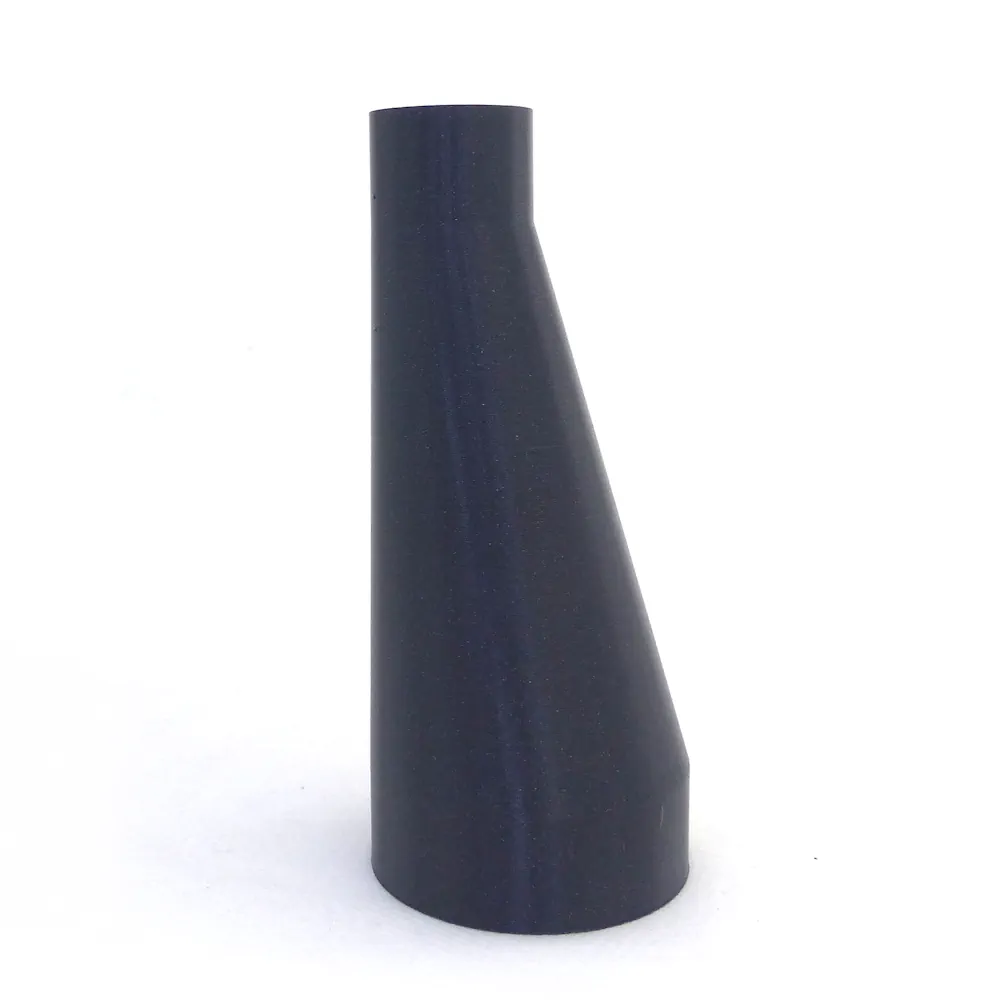
Here, an "inline tube adapter" refers to an accessory designed to connect two cylindrical tubes of different diameters. This does not refer to a Y-connector or an elbow fitting. The two tubes are parallel (inline), but not necessarily on the same axis, as we’ll see later.
Other terms may include reducer, tube joint, connector, coupler, sleeve, straight adapter, etc.
The modeling is based on a first cylinder called tube A, a second cylinder called tube B, and a transition that ensures the connection between the two tubes. The adapter's inlet and outlet can be considered either male or female.
And good news, on-demand generation is available for this template!
Detailed parameters
For each tube, the following parameters are available:
- tube length
- outer diameter of the tube
- tube thickness
These names are self-explanatory. The inner diameter of a tube equals the outer diameter minus 2×thickness. For example, a tube with a 20 mm diameter and 3 mm thickness will have an inner diameter of 20 – 2×3 = 14 mm. Tube B must have a strictly smaller diameter than tube A. Obviously, the wall thickness must be strictly less than half of the diameter; otherwise, the tube would be solid... One important note about diameters: a tube with an outer diameter of 50 mm won’t fit into a tube with an inner diameter of 50 mm. You need to leave a margin — especially in the context of 3D printing.
Then comes the concept of transition. The transition represents the connection interface between the two tubes. This parameter is available for on-demand generation, but the minimum allowed value is 5 mm.
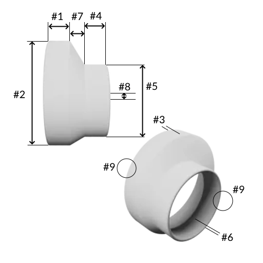
Next comes an interesting parameter: the axis offset. With a value of 0, the centers of both tubes will be aligned on the same axis. If set to 6 mm, for example, tube B will be offset by 6 mm from tube A’s axis. Note that the offset will be automatically limited by the generation engine to ensure that the smaller tube always fits within the internal footprint of the larger tube.
Finally, the "ends fillet" parameter allows the ends to be “rounded” to make it easier to insert the tubes into the adapter. Four options are available:
- 0: no fillet
- 1: fillet on the outside of the ends
- 2: fillet on the inside of the ends
- 3: fillet on both the inside and outside of the ends
How to get a female end?
A simple calculation is needed.
Suppose you want the output (tube B) to have a female diameter of 40 mm (to insert a 40 mm tube inside).
Now let’s say you want a tube thickness of 5 mm.
That means the outer diameter of tube B must be 40 mm + 5 mm + 5 mm = 50 mm. Got it?
As mentioned earlier, it’s important to leave some margin — let’s say 1 mm. So for parameter #5 diameter side B, you should enter 51 mm. That’s the case of model Reducer ⌀100 to 40 mm female (#1098).
The formula to calculate the required outer diameter based on the expected inner diameter is:
outer diameter (parameter #2 or #5) = expected inner diameter + 2 × thickness + 0.1 (margin)
Focus on modeling
Let’s get a bit technical.
As for modeling the tubes themselves, nothing special here.
The transition is created using a "loft" between the top profile of tube A and the bottom profile of tube B. The distance between these two profiles is determined by the value assigned to the transition parameter.
The ends fillets are always equal to: (thickness value / 2) – 0.1. For example, if the thickness is set to 3 mm, the fillet will have a radius of (3/2) – 0.1 = 1.4 mm. Still in this example, if the ends fillets parameter is set to 3, two fillets of 1.4 mm radius each will be modeled.
The most complex part concerns the generation of the adapter’s “central” fillets. The adapter has 4 internal edges and 4 external edges. The end edges are managed by the ends fillets parameter as explained earlier. Remaining are the edges related to the transition — 2 inside, 2 outside. The dimensions of these fillets are handled automatically by the generation engine. These fillets will always be smaller than the thinnest wall thickness among the two tubes. Additionally, a maximum value is defined for these fillets:
- 3 mm maximum for external fillets
- 5 mm for internal fillets
Note that the engine automatically evaluates whether these fillets can be generated. In some cases, this is not possible, and the model will be rendered without one or more of the fillets on the transition.
Now you know everything!
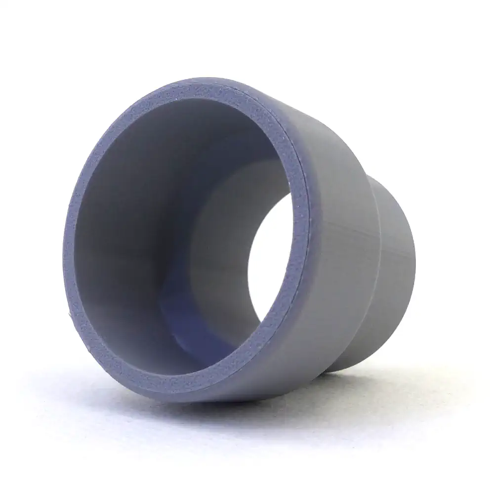
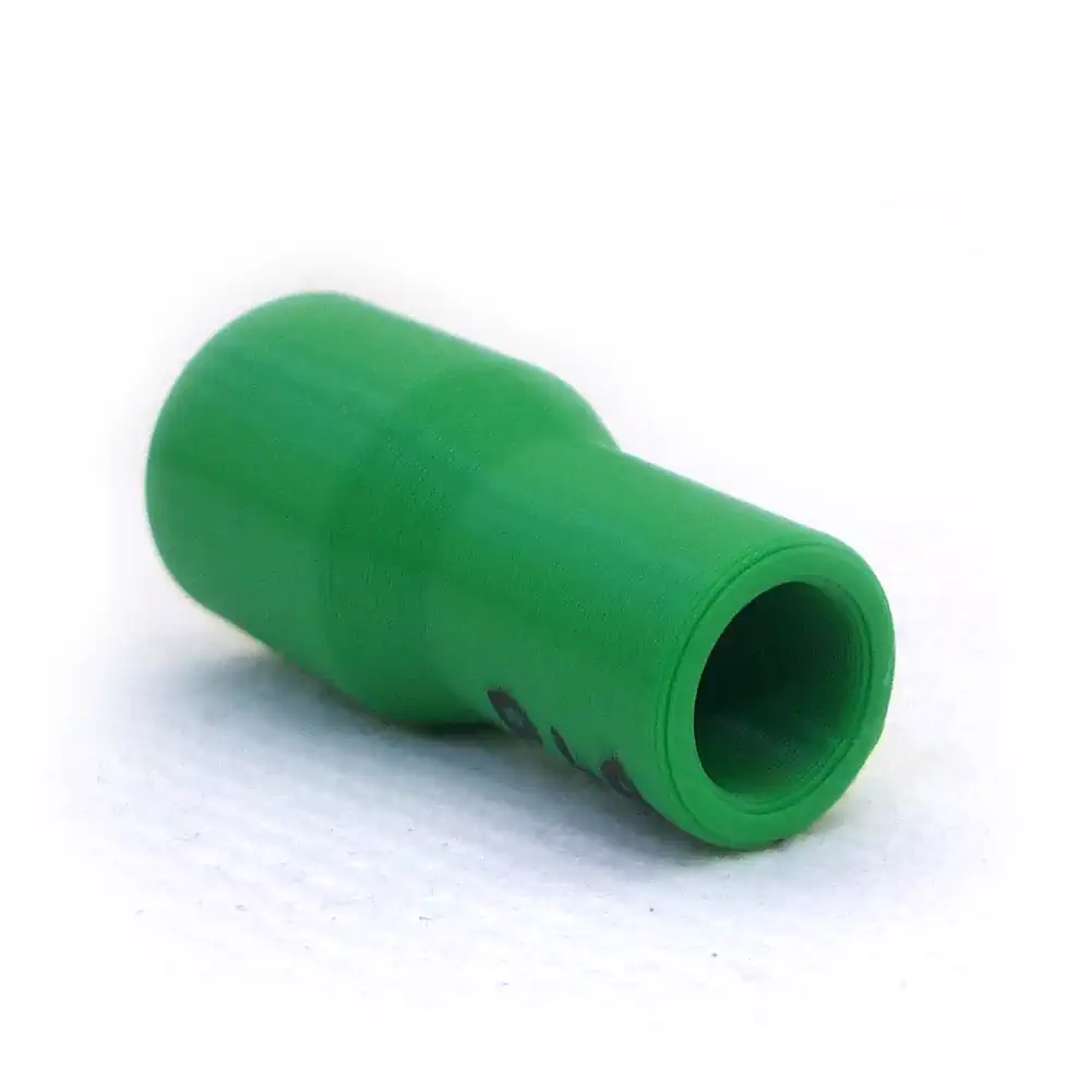
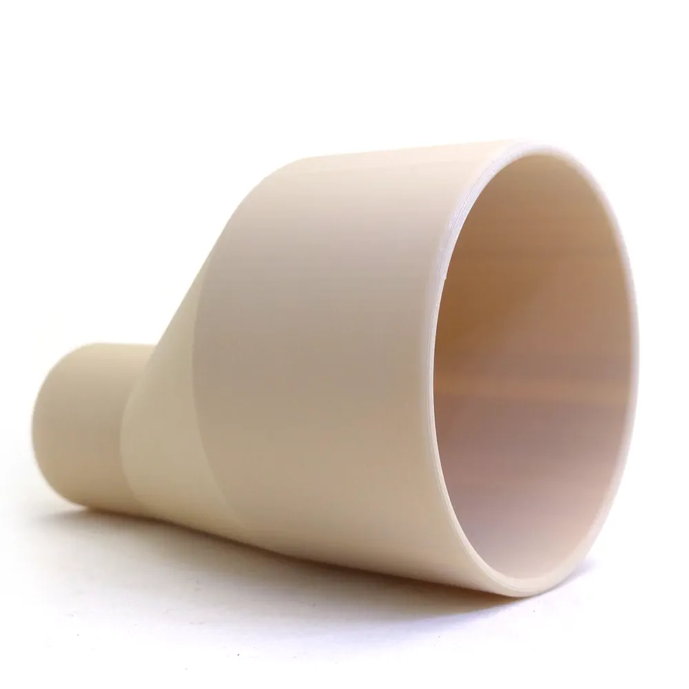
Some connector examples
Here are some 3D prints based on models generated using this template.
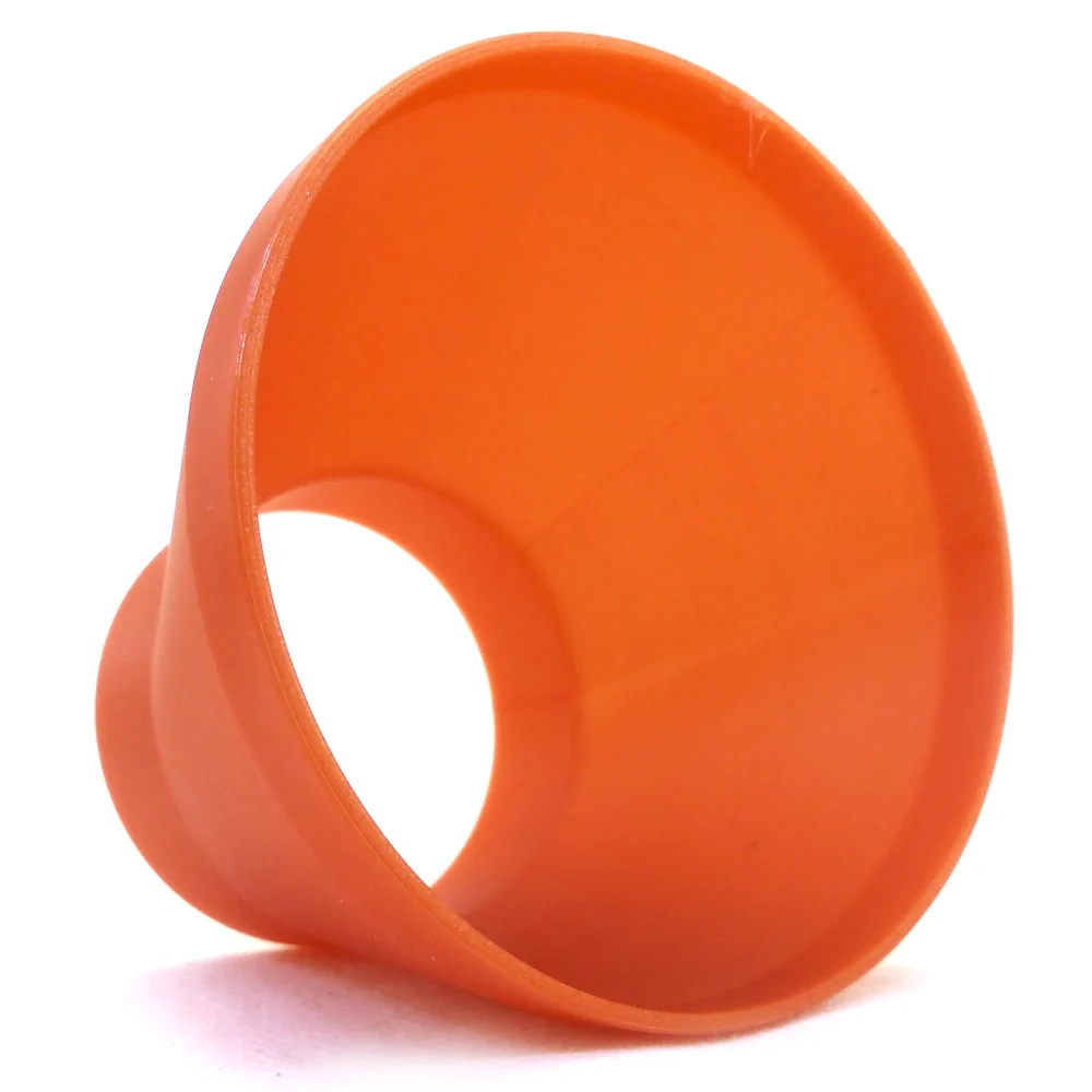
Now it’s your turn to take the controls!