How 3D Models Are Generated Using build123d
Discover how 3D files are modeled with build123d under Python, the open-source parametric modeling library used on iteration3d.
build123d as the core engine
On iteration3d, the main 3D file generation engine is based on the tool build123d.
It is an open-source Python program for parametric modeling under the Apache 2.0 License. This framework is built on the Open Cascade geometry kernel (OCCT - maintained by Capgemini). The popular open-source modeling software FreeCAD uses this same core. build123d can be considered an evolution of CadQuery.
Note : although this is not the focus here, the thumbnails and carousels are generated using Blender .
What is code-driven parametric modeling?
When using tools like Fusion 360 or SolidWorks, you're used to drawing a sketch with a mouse or stylus and then extruding it to get a 3D shape. Script-based parametric modeling works differently — instead of “drawing in 3D,” you actually program in 3D. Fusion 360 and SolidWorks are indeed parametric modelers under the hood: you can change a dimension or adjust an extrusion value at any time. On top of that, they provide a graphical interface that makes the whole process much easier for the user.
Let’s get back to our topic: parametric modeling through code. OpenSCAD is a program based on this principle and serves as an accessible entry point to parametric modeling. To put it simply, each "shape" is declared programmatically. In OpenSCAD, the instruction cube([10, 10, 10]) will generate a cube (as you’ve guessed) of 10x10x10. Easy, right? Create another cube, move it with another command, and gradually your program creates a new 3D object.
build123d follows the same principle, in a more complete and therefore more complex way — or maybe not. The build123d documentation even includes a transition tutorial from OpenSCAD.
The power of Python in build123d
The main strength of build123d lies in its full use of the powerful Python programming language. We'll stop here, as the goal of this page is educational, but developers will see the potential of this coding language when applied to parametric modeling.
As an example, the following build123d code will produce a rectangular prism measuring 100 x 42 x 57 mm (Model #768):
from build123d import *

with BuildPart() as thisObject:
    Box(100, 42, 57)
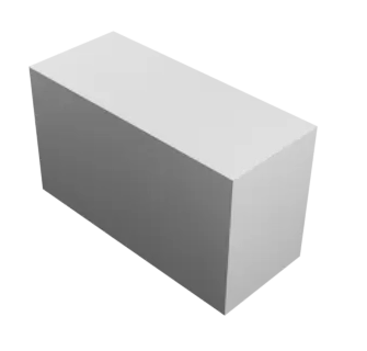
Of course, there’s a whole set of instructions to move, merge, subtract, and more. This allows you to generate very complex 3D shapes — and more importantly, to do so in a parametric way, meaning the model is easily modifiable by simply adjusting the variables you've defined.
How to Get Started with build123d?
To start modeling with build123d, you will need to have some simple but essential knowledge of Python programming.
Build123d provides detailed documentation.
The best starting point is probably this simple and well-structured tutorial on designing a 3D part with Build123d. Then, many additional examples are available.
Build123d has a very responsive Discord channel, with regular contributions from the project’s developers.
To greatly facilitate debugging, it is very useful to install the graphical interface OCP CAD Viewer for VS Code, which integrates very easily and directly into Visual Studio Code.
You can find the official build123d GitHub repository here.
And to conclude: thank you build123d, thank you CadQuery, thank you OCCT, thank you Python!
Complete build123d Tutorial
For this tutorial, we’ll use the 3D Bowl / Pot template as our reference. As noted above, we use Visual Studio Code as the source code editor, and OCP CAD Viewer for VS Code to visualize on-screen the sketches and models we produce. The screenshots shown in this tutorial come from OCP CAD Viewer for VS Code.
Define the parameters and import the tools
Let’s assume we want to define our bowl with these parameters:
- inner_bottom_diam for the inner diameter at the base of the bowl
- inner_top_diam for the inner diameter at the top of the bowl
- inner_height for the inner height of the bowl
- thickness for the total wall thickness
This is a decisive step that will determine the entire code construction. You can consult On-demand 3D file generation: the process to learn more about this first step, which is part of an overall workflow.
We also want the base of the bowl rounded at the corner, so we introduce a new variable bend_fillet and set it to 1.
That gives us these initial lines of code:
from build123d import *
from ocp_vscode import show

from math import atan2, tan, pi

# --- Inputs ---
inner_bottom_diam = 50
inner_top_diam    = 80
inner_height      = 70
thickness         = 2

bend_fillet       = 1.0
From these first lines, we’re aiming for a bowl with a wall thickness of 2, an inner height of 70, an inner bottom diameter of 50, and an inner top diameter of 80.
You’ll notice several lines starting with import. These import the Python libraries the script needs:
from build123d import *– imports all functions from Build123d, the parametric 3D modeling library used to create geometry.from ocp_vscode import show– imports the show() function from ocp_vscode, which displays 3D models directly in VS Code.from math import atan2, tan– imports functions from the standard math library for trigonometric and geometric calculations.
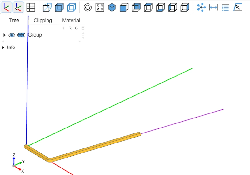
Draw a path
We want to generate a bowl. A bowl is a symmetrical shape around a central axis: it can be created by revolving a 2D profile, whose rotation produces a perfectly regular geometry around that axis. So first, we’ll generate a path that will later serve as the basis for the revolution.
This path will be defined by three points. The first is at the origin (0.0, 0.0) and the second lies along the X-axis, at a distance of inner_bottom_diam from the origin (inner_bottom_diam / 2.0, 0.0). We divide by two to get the radius from the diameter.
For the third point (the top of the bowl), things are a bit more complex. We’ve decided that the bowl’s rim will be parallel to the base (parallel to the X-axis), not tilted. That’s tricky to picture and explain at this stage, so we’ll intentionally place the third point at twice the intended height—in other words, twice the inner height, inner_height. To be able to “stretch” this segment, we’ll compute the angle implied by the bowl’s dimensions. Then, depending on whether that angle is vertical or not, we’ll apply specific handling.
This yields the following code:
from build123d import *
from ocp_vscode import show

from math import atan2, tan

# --- Inputs ---
inner_bottom_diam = 50
inner_top_diam    = 80
inner_height      = 70
thickness         = 2


bend_fillet       = 1.0


x0, y0 = 0.0, 0.0
x1, y1 = inner_bottom_diam / 2.0, 0.0

dx0 = (inner_top_diam - inner_bottom_diam) / 2.0
dy0 = inner_height
angle_rad = atan2(dy0, dx0)

y2 = inner_height * 2.0
if abs(dx0) < 1e-9: # vertical wall case (top==bottom)
    x2 = x1
else:
    x2 = x1 + y2 / tan(angle_rad)
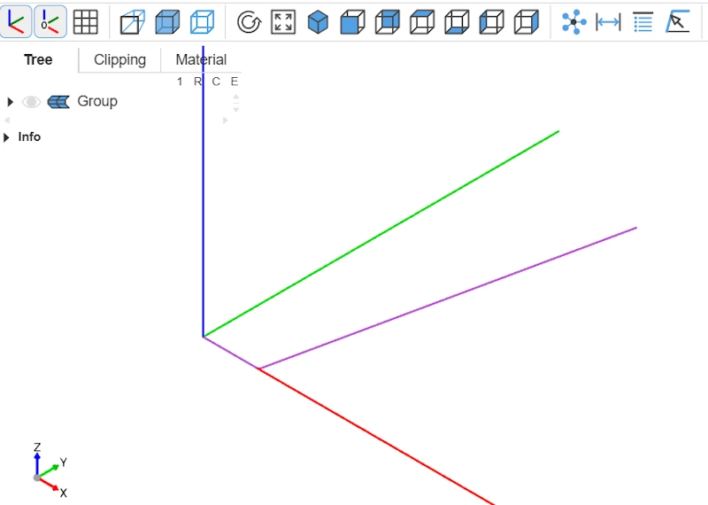
Now that we have the three points, we can build the path. To do this, we use FilletPolyline, which creates a path with a fillet (a rounded corner) so the base of our bowl is softened. FilletPolyline is the first construction function we use in our script. show lets us visualize the path, in purple on screen.
from build123d import *
from ocp_vscode import show

from math import atan2, tan

# --- Inputs ---
inner_bottom_diam = 50
inner_top_diam    = 80
inner_height      = 70
thickness         = 2


bend_fillet       = 1.0


x0, y0 = 0.0, 0.0
x1, y1 = inner_bottom_diam / 2.0, 0.0

dx0 = (inner_top_diam - inner_bottom_diam) / 2.0
dy0 = inner_height
angle_rad = atan2(dy0, dx0)

y2 = inner_height * 2.0
if abs(dx0) < 1e-9: # vertical wall case (top==bottom)
    x2 = x1
else:
    x2 = x1 + y2 / tan(angle_rad)

# 1) Filleted polyline (wire path)
with BuildLine() as ln:
    FilletPolyline((x0, y0), (x1, y1), (x2, y2), radius=bend_fillet)
path = ln.wire()

show(path)
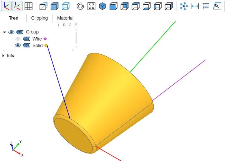
Extrude a 3D shape
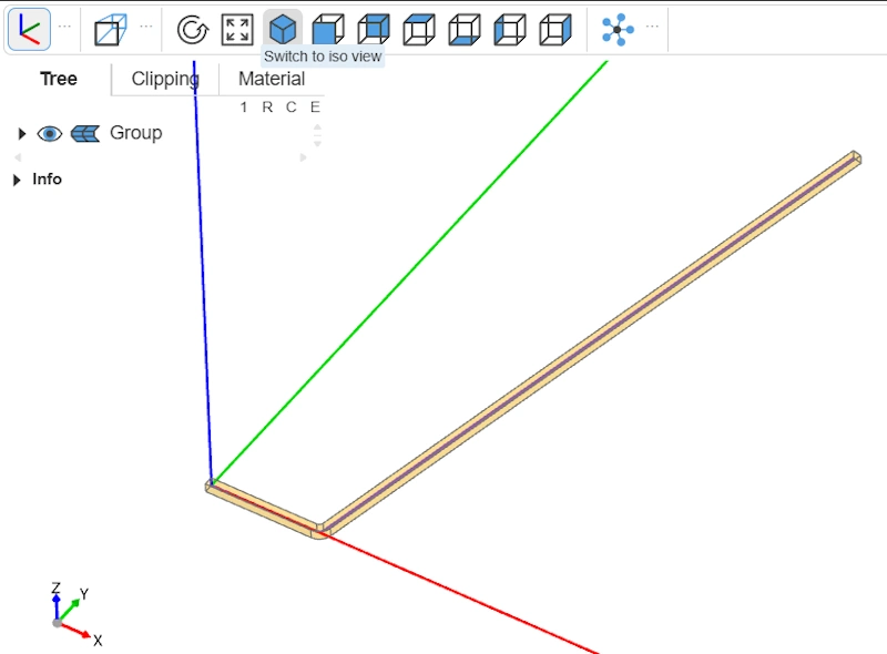
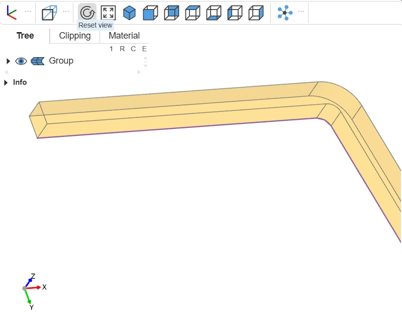
To revolve around the Y-axis, we need a 2D profile—a closed shape, a face. Our path is only a segment. So we’ll “extrude” a square along this path to obtain a kind of bent 3D bar.
To do this, we use the Rectangle and sweep construction functions. Rectangle defines a 2D rectangle (here a square, since length equals width) with side thickness, the desired wall thickness of our bowl. sweep “sweeps” the square profile along the path to create a 3D shape—a bent bar shown in transparency thanks to transparent=True.
from build123d import *
from ocp_vscode import show

from math import atan2, tan

# --- Inputs ---
inner_bottom_diam = 50
inner_top_diam    = 80
inner_height      = 70
thickness         = 2


bend_fillet       = 1.0


x0, y0 = 0.0, 0.0
x1, y1 = inner_bottom_diam / 2.0, 0.0

dx0 = (inner_top_diam - inner_bottom_diam) / 2.0
dy0 = inner_height
angle_rad = atan2(dy0, dx0)

y2 = inner_height * 2.0
if abs(dx0) < 1e-9: # vertical wall case (top==bottom)
    x2 = x1
else:
    x2 = x1 + y2 / tan(angle_rad)

# 1) Filleted polyline (wire path)
with BuildLine() as ln:
    FilletPolyline((x0, y0), (x1, y1), (x2, y2), radius=bend_fillet)
path = ln.wire()


# 2) Sweep a square section along that path
with BuildPart() as swept:
    with BuildSketch(path ^ 0):
        Rectangle(thickness, thickness, align=(Align.MAX, Align.MIN))
    sweep(path=path, transition=Transition.RIGHT)

show(path, swept, transparent=True)
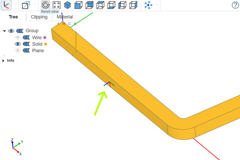
Trim the 3D shape
Recall that we “stretched” the inclined arm. Now we need to trim it. We set the cut height to thickness + inner_height—that is, wall thickness plus inner height. This will be the bowl’s total height.
If you look closely at the 3D shape at this stage, you’ll see it isn’t aligned along X but shifted by thickness below the X-axis. The simplest approach would be to move the part toward +Y by thickness. But we’ll do it differently to introduce how to locate a specific face.
If we want to cut at thickness + inner_height, we need to position ourselves under the 3D shape. Here we use filter_by(Plane.XZ) to select only the faces parallel to the XZ plane of the swept part. Then we sort them by their position along the Y-axis with sort_by(Axis.Y) to get the lowest face, which will serve as our reference.
...

# 3) Cut the angled arm using a plane parallel to XZ
target_y = thickness + inner_height

# Pick the lowest XZ-parallel face as a reference
xz_faces = swept.part.faces().filter_by(Plane.XZ).sort_by(Axis.Y)

ref_face = xz_faces[0]  # EN: lowest-Y face

# Build a reference plane from that face
ref_plane = Plane(ref_face)

show(path,swept.part,ref_plane)

...
Now we want to ensure that the reference plane’s normal points upward, that is, in the +Y direction, like the standard Plane.XZ. If the normal is oriented the other way (toward −Y), we invert it. Then we compute the offset distance between the plane’s current position and the target height Y = thickness + inner_height. This lets us create a new offset plane (cut_plane) at exactly the right height to perform the cut. We then trim our 3D shape with split.
from build123d import *
from ocp_vscode import show

from math import atan2, tan

# --- Inputs ---
inner_bottom_diam = 50
inner_top_diam    = 80
inner_height      = 70
thickness         = 2


bend_fillet       = 1.0


x0, y0 = 0.0, 0.0
x1, y1 = inner_bottom_diam / 2.0, 0.0

dx0 = (inner_top_diam - inner_bottom_diam) / 2.0
dy0 = inner_height
angle_rad = atan2(dy0, dx0)

y2 = inner_height * 2.0
if abs(dx0) < 1e-9: # vertical wall case (top==bottom)
    x2 = x1
else:
    x2 = x1 + y2 / tan(angle_rad)

# 1) Filleted polyline (wire path)
with BuildLine() as ln:
    FilletPolyline((x0, y0), (x1, y1), (x2, y2), radius=bend_fillet)
path = ln.wire()


# 2) Sweep a square section along that path
with BuildPart() as swept:
    with BuildSketch(path ^ 0):
        Rectangle(thickness, thickness, align=(Align.MAX, Align.MIN))
    sweep(path=path, transition=Transition.RIGHT)


# 3) Cut the angled arm using a plane parallel to XZ
target_y = thickness + inner_height

# Pick the lowest XZ-parallel face as a reference
xz_faces = swept.part.faces().filter_by(Plane.XZ).sort_by(Axis.Y)

ref_face = xz_faces[0]  # EN: lowest-Y face

# Build a reference plane from that face
ref_plane = Plane(ref_face)

show(path,swept.part,ref_plane)

# Ensure the plane's normal points to +Y (same convention as Plane.XZ) so Keep.TOP keeps the upper side
if ref_plane.z_dir.dot(Vector(0, 1, 0)) < 0:
    ref_plane = Plane(ref_plane.origin, ref_plane.x_dir, -ref_plane.z_dir)

# Compute the signed offset to reach target Y (thickness + inner_height)
offset_dist = target_y - ref_plane.origin.Y
cut_plane = ref_plane.offset(offset_dist)


with BuildPart() as trimmed:
    add(swept.part)
    split(bisect_by=cut_plane, keep=Keep.BOTTOM)

final_part = trimmed.part

show(path,final_part)
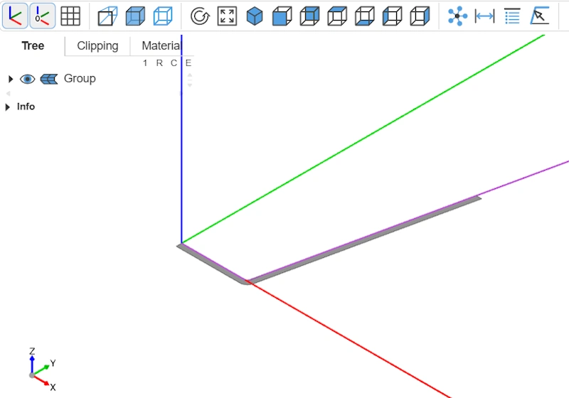
Prepare the revolve face
Remember, the goal of building this bent 3D bar is to get a profile we can rotate around the Y-axis. But you can’t revolve a solid directly. So we’ll extract the bar’s face that lies on the XY plane.
...
# 4) Get the seed_face (face lying on the XY plane, i.e., Z ≈ 0)
xy_faces = final_part.faces().filter_by(Plane.XY)

# Pick the XY face whose plane is closest to Z = 0
seed_face = min(xy_faces, key=lambda f: abs(Plane(f).origin.Z))

show(path,seed_face)
...
Revolution (revolve)
Here we are! We can now apply the revolution with revolve.
from build123d import *
from ocp_vscode import show

from math import atan2, tan

# --- Inputs ---
inner_bottom_diam = 50
inner_top_diam    = 80
inner_height      = 70
thickness         = 2


bend_fillet       = 1.0


x0, y0 = 0.0, 0.0
x1, y1 = inner_bottom_diam / 2.0, 0.0

dx0 = (inner_top_diam - inner_bottom_diam) / 2.0
dy0 = inner_height
angle_rad = atan2(dy0, dx0)

y2 = inner_height * 2.0
if abs(dx0) < 1e-9: # vertical wall case (top==bottom)
    x2 = x1
else:
    x2 = x1 + y2 / tan(angle_rad)

# 1) Filleted polyline (wire path)
with BuildLine() as ln:
    FilletPolyline((x0, y0), (x1, y1), (x2, y2), radius=bend_fillet)
path = ln.wire()


# 2) Sweep a square section along that path
with BuildPart() as swept:
    with BuildSketch(path ^ 0):
        Rectangle(thickness, thickness, align=(Align.MAX, Align.MIN))
    sweep(path=path, transition=Transition.RIGHT)


# 3) Cut the angled arm using a plane parallel to XZ
target_y = thickness + inner_height

# Pick the lowest XZ-parallel face as a reference
xz_faces = swept.part.faces().filter_by(Plane.XZ).sort_by(Axis.Y)

ref_face = xz_faces[0]  # EN: lowest-Y face

# Build a reference plane from that face
ref_plane = Plane(ref_face)

# Ensure the plane's normal points to +Y (same convention as Plane.XZ) so Keep.TOP keeps the upper side
if ref_plane.z_dir.dot(Vector(0, 1, 0)) < 0:
    ref_plane = Plane(ref_plane.origin, ref_plane.x_dir, -ref_plane.z_dir)

# Compute the signed offset to reach target Y (thickness + inner_height)
offset_dist = target_y - ref_plane.origin.Y
cut_plane = ref_plane.offset(offset_dist)


with BuildPart() as trimmed:
    add(swept.part)
    split(bisect_by=cut_plane, keep=Keep.BOTTOM)

final_part = trimmed.part


# 4) Get the seed_face (face lying on the XY plane, i.e., Z ≈ 0)
xy_faces = final_part.faces().filter_by(Plane.XY)

# Pick the XY face whose plane is closest to Z = 0
seed_face = min(xy_faces, key=lambda f: abs(Plane(f).origin.Z))


# 5) Revolve the seed_face into a solid bowl
with BuildPart() as revolved:
    revolve(seed_face, axis=Axis.Y)
final_part = revolved.part

show(path,final_part)
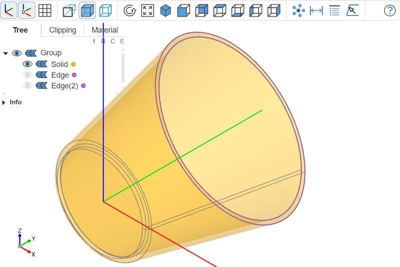
Apply fillets
The rim edges are still sharp. We’ll apply a fillet—for aesthetics, but also to address the sometimes confusing fillet selection problem. Unlike Fusion 360, where a simple click on the edge suffices, here we must locate those edges programmatically. In our example this is fairly simple, but for complex models it can be much more tedious.
We’ll filter all the solid’s edges to keep only those of circular type (GeomType.CIRCLE), then sort them by their position along the Y-axis to isolate the two highest edges that form the bowl’s rim.
...
# 6) Select the two highest circular edges in Y
edges_sorted = (
    final_part.edges()
    .filter_by(GeomType.CIRCLE)               # keep only circular edges
    .sort_by(Axis.Y)                          # sort by Y position
)
target_edges = edges_sorted[-2:]              # take the two highest

show(target_edges)
...
All that’s left is to add the fillets with fillet, which gives us the final code below:
from build123d import *
from ocp_vscode import show

from math import atan2, tan

# --- Inputs ---
inner_bottom_diam = 50
inner_top_diam    = 80
inner_height      = 70
thickness         = 2


bend_fillet       = 1.0


x0, y0 = 0.0, 0.0
x1, y1 = inner_bottom_diam / 2.0, 0.0

dx0 = (inner_top_diam - inner_bottom_diam) / 2.0
dy0 = inner_height
angle_rad = atan2(dy0, dx0)

y2 = inner_height * 2.0
if abs(dx0) < 1e-9: # vertical wall case (top==bottom)
    x2 = x1
else:
    x2 = x1 + y2 / tan(angle_rad)

# 1) Filleted polyline (wire path)
with BuildLine() as ln:
    FilletPolyline((x0, y0), (x1, y1), (x2, y2), radius=bend_fillet)
path = ln.wire()


# 2) Sweep a square section along that path
with BuildPart() as swept:
    with BuildSketch(path ^ 0):
        Rectangle(thickness, thickness, align=(Align.MAX, Align.MIN))
    sweep(path=path, transition=Transition.RIGHT)


# 3) Cut the angled arm using a plane parallel to XZ
target_y = thickness + inner_height

# Pick the lowest XZ-parallel face as a reference
xz_faces = swept.part.faces().filter_by(Plane.XZ).sort_by(Axis.Y)

ref_face = xz_faces[0]  # EN: lowest-Y face

# Build a reference plane from that face
ref_plane = Plane(ref_face)

# Ensure the plane's normal points to +Y (same convention as Plane.XZ) so Keep.TOP keeps the upper side
if ref_plane.z_dir.dot(Vector(0, 1, 0)) < 0:
    ref_plane = Plane(ref_plane.origin, ref_plane.x_dir, -ref_plane.z_dir)

# Compute the signed offset to reach target Y (thickness + inner_height)
offset_dist = target_y - ref_plane.origin.Y
cut_plane = ref_plane.offset(offset_dist)


with BuildPart() as trimmed:
    add(swept.part)
    split(bisect_by=cut_plane, keep=Keep.BOTTOM)

final_part = trimmed.part


# 4) Get the seed_face (face lying on the XY plane, i.e., Z ≈ 0)
xy_faces = final_part.faces().filter_by(Plane.XY)

# Pick the XY face whose plane is closest to Z = 0
seed_face = min(xy_faces, key=lambda f: abs(Plane(f).origin.Z))


# 5) Revolve the seed_face into a solid bowl
with BuildPart() as revolved:
    revolve(seed_face, axis=Axis.Y)
final_part = revolved.part


# 6) Select the two highest circular edges in Y
with BuildPart() as fp:
    add(final_part)
    edges_sorted = (
        fp.part.edges()
        .filter_by(GeomType.CIRCLE)
        .sort_by(Axis.Y)
    )
    target_edges = edges_sorted[-2:]
    fillet(target_edges, 0.6)

show(fp)
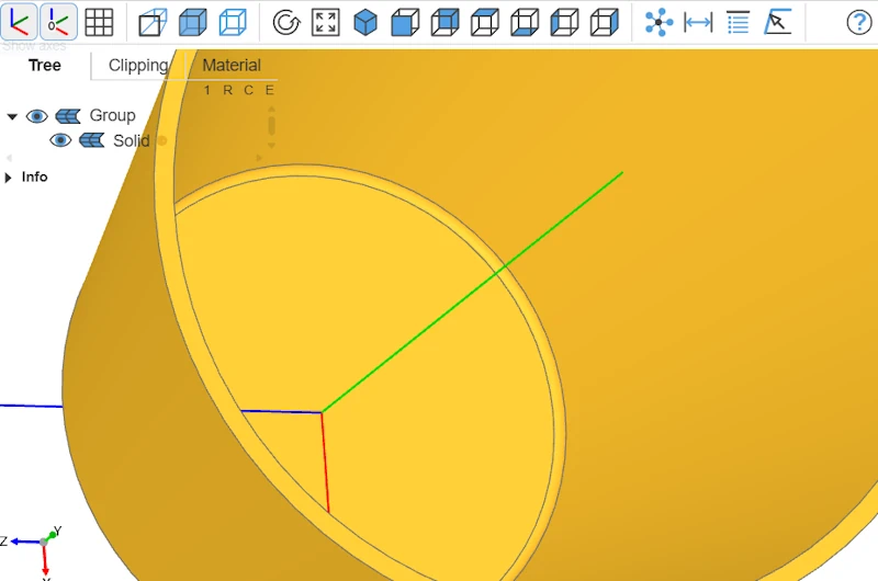
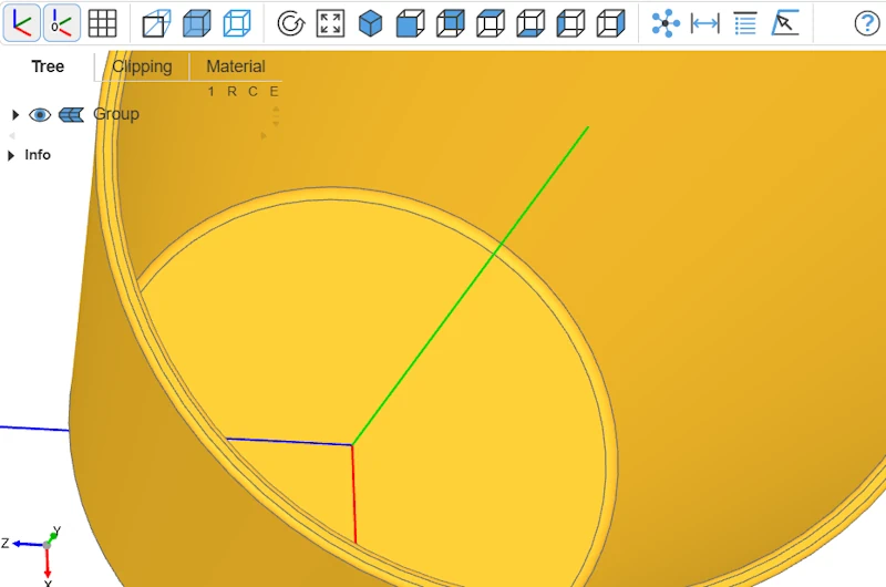
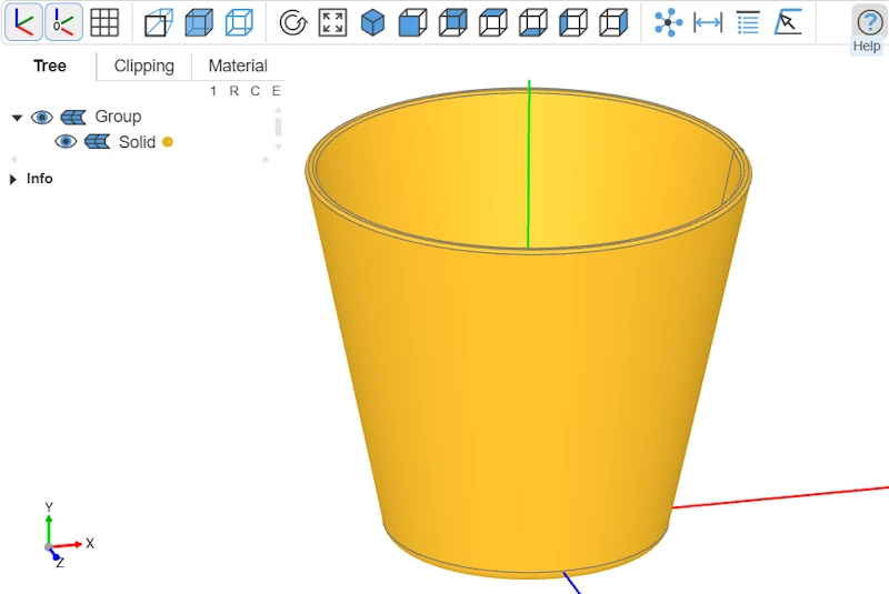
Final object
And that’s it—our bowl is modeled!
As mentioned at the outset, this isn’t the simplest or fastest way
to obtain this 3D volume.
The idea was to explore as many construction
functions as possible in this context and to give an overview of the build123d workflow.
There are many other construction functions we didn’t use here. We also didn’t cover
algebra mode.
Time to explore further and make the most of this very powerful library!