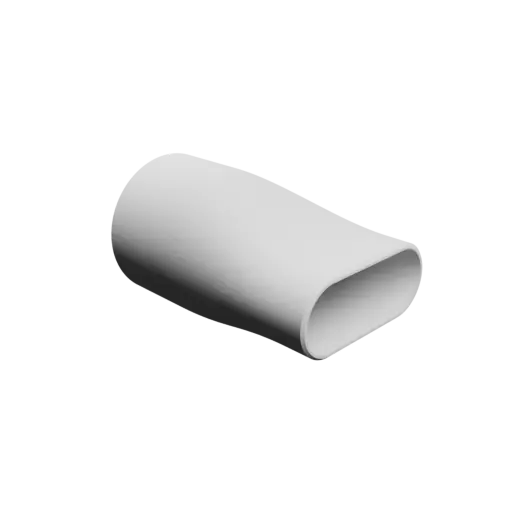
Custom Oval hose adapter STL file 90.1x90 mm to 100x40 mm – transition: 100 mm 📦#4332
Generation date: 2025-12-05

3D model download
Free- oval-duct-transition-fitting-w_model4332-nb0_dd{id}.stl : 2 Mo
STL
Mesh quality :
0.0005
0.05
 No compliance warranty
 License: ITE IPU v1.0 - Iteration3d
(Internal and private use, non-commercial – no distribution – no derivatives)
Safe download
Values for this model
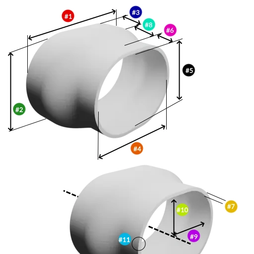
This model was generated by the Oval duct transition fitting / hose-shaped reducer template, with the following values:
| Parameter | Value | |
|---|---|---|
| #1 | side A internal width | 90.1 mm (≃3 9/16 in) |
| #2 | side A internal height | 90 mm (≃3.54 in) |
| #3 | sleeve length on side A | 50 mm (≃1.97 in) |
| #4 | side B internal width | 100 mm (≃3 15/16 in) |
| #5 | side B internal height | 40 mm (≃1 9/16 in) |
| #6 | sleeve length on side B | 20 mm (≃0.79 in) |
| #7 | thickness | 3 mm (≃1/8 in) |
| #8 | transition length | 100 mm (≃3 15/16 in) |
| #9 | Y offset | 0 mm (0 in) |
| #10 | Z offset | 0 mm (0 in) |
| #11 | end chamfers | outside |
| Metadata | Value |
|---|---|
| external width on side A | 96.1 mm (≃3.78 in) |
| external height on side A | 96 mm (≃3.78 in) |
| external width on side B | 106 mm (≃4 3/16 in) |
| external height on side B | 46 mm (≃1 13/16 in) |
| total length | 170 mm (≃6 11/16 in) |
Parameter overview
Labels are used in the naming of the downloaded 3D files.
| Parameter | Label |
|---|---|
| #1 side A internal width | widOA |
| #2 side A internal height | heiOA |
| #3 sleeve length on side A | lenSA |
| #4 side B internal width | widOB |
| #5 side B internal height | heiOB |
| #6 sleeve length on side B | lenSB |
| #7 thickness | thi |
| #8 transition length | tra |
| #9 Y offset | ofsY |
| #10 Z offset | ofsZ |
| #11 end chamfers | cha |
Related 3D models
To search for a model based on your own parameters, go to the template page Oval duct transition fitting / hose-shaped reducer
Oval duct transition adapter STL 3D file 73x30 mm to 65x35 mm – transition: 150 mm (📦 #10814)
1 object(s) - format STL
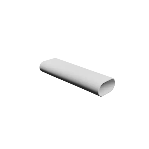
Oval duct transition adapter in STL 3D file format. The internal cross-section on side A is 73x30 mm, while on side B it is 65x35 mm. The useful lengths are 30 mm (A) and 50 mm (B), respectively. The transition section between the two ends is 150 mm long, for an overall length of 230 mm (sleeve A, transition and sleeve B). The external edges at the ends are chamfered, which simplifies inserting the adapter into the duct.
| Parameter | Value | Unit |
|---|---|---|
| side A internal width | 73 | mm |
| side A internal height | 30 | mm |
| sleeve length on side A | 30 | mm |
| side B internal width | 65 | mm |
| side B internal height | 35 | mm |
| sleeve length on side B | 50 | mm |
| thickness | 2 | mm |
| transition length | 150 | mm |
| Y offset | 0 | mm |
| Z offset | 0 | mm |
| end chamfers | outside |
Oval duct transition adapter STL 3D file 110.1x110 mm to 180x40 mm – transition: 20 mm (📦 #10649)
1 object(s) - format STL
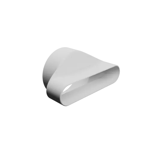
STL 3D file for an oval duct adapter. On side A, the internal cross-section is 110.1x110 mm (nearly circular), whereas on side B it is 180x40 mm (oval). A uniform useful length of 40 mm is available on both sleeves. The transition portion extends over 20 mm and the overall length, sleeves included, is 100 mm. External chamfers at the ends help with engagement and assembly within the duct system.
| Parameter | Value | Unit |
|---|---|---|
| side A internal width | 110.1 | mm |
| side A internal height | 110 | mm |
| sleeve length on side A | 40 | mm |
| side B internal width | 180 | mm |
| side B internal height | 40 | mm |
| sleeve length on side B | 40 | mm |
| thickness | 2 | mm |
| transition length | 20 | mm |
| Y offset | 0 | mm |
| Z offset | 0 | mm |
| end chamfers | outside |
Oval duct transition fitting STL file 105x35 mm to 105x34 mm – transition: 20 mm (📦 #8809)
1 object(s) - format STL
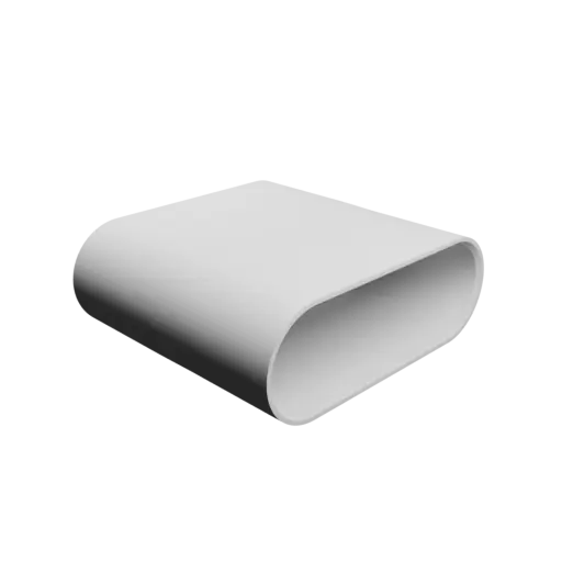
Oval hose adapter provided as a STL 3D file. On side A, the internal cross-section is 105x35 mm, whereas on side B it is 105x34 mm. The useful sleeve length is the same on both sides, 40 mm. The transition links the two ends over 20 mm, with a total overall length of 100 mm. Internal chamfers are added at the ends to make assembly and duct insertion easier.
| Parameter | Value | Unit |
|---|---|---|
| side A internal width | 105 | mm |
| side A internal height | 35 | mm |
| sleeve length on side A | 40 | mm |
| side B internal width | 105 | mm |
| side B internal height | 34 | mm |
| sleeve length on side B | 40 | mm |
| thickness | 3 | mm |
| transition length | 20 | mm |
| Y offset | 0 | mm |
| Z offset | 0 | mm |
| end chamfers | inside |
Oval hose adapter STL file 130x90 mm to 100x40 mm – transition: 100 mm (📦 #4335)
1 object(s) - format STL
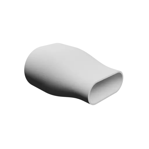
STL 3D file for an oval adapter. The internal cross-section on side A is 130x90 mm, while on side B it is 100x40 mm. The useful sleeve length on side A is 50 mm, while on side B it reaches 20 mm. The transition section between the two ends is 100 mm long, for an overall length of 170 mm (sleeve A, transition and sleeve B). No chamfer is applied at the ends, so both the inner and outer edges remain sharp.
| Parameter | Value | Unit |
|---|---|---|
| side A internal width | 130 | mm |
| side A internal height | 90 | mm |
| sleeve length on side A | 50 | mm |
| side B internal width | 100 | mm |
| side B internal height | 40 | mm |
| sleeve length on side B | 20 | mm |
| thickness | 3 | mm |
| transition length | 100 | mm |
| Y offset | 0 | mm |
| Z offset | 0 | mm |
| end chamfers | none |
Oval duct transition adapter STL 3D file 52x39 mm to 47x46 mm – transition: 20 mm (📦 #6016)
1 object(s) - format STL
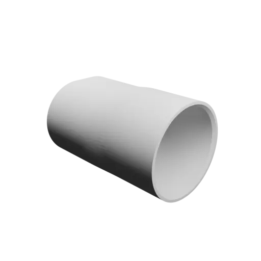
Oval pipe adapter in STL 3D file format. The internal cross-section on side A is 52x39 mm (oval), while on side B it is 47x46 mm (nearly circular). The useful sleeve length is the same on both sides, 30 mm. The transition section is 20 mm long, for a final overall length of 80 mm. The internal edges at the ends are chamfered to help guide the duct during insertion.
| Parameter | Value | Unit |
|---|---|---|
| side A internal width | 52 | mm |
| side A internal height | 39 | mm |
| sleeve length on side A | 30 | mm |
| side B internal width | 47 | mm |
| side B internal height | 46 | mm |
| sleeve length on side B | 30 | mm |
| thickness | 3 | mm |
| transition length | 20 | mm |
| Y offset | 0 | mm |
| Z offset | 0 | mm |
| end chamfers | inside |
Oval duct transition adapter STL file 52x40 mm to 44x43 mm – transition: 20 mm (📦 #6034)
1 object(s) - format STL
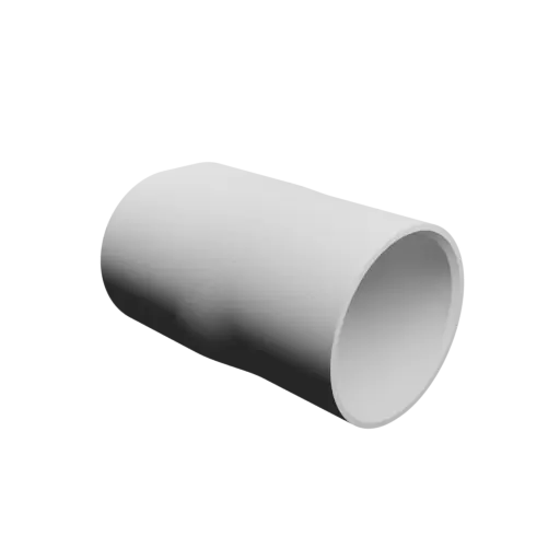
Oval hose adapter in STL 3D file format. On side A, the internal cross-section is 52x40 mm (oval), whereas on side B it is 44x43 mm (nearly circular). Each sleeve provides a useful length of 30 mm. Between the two sleeves, the transition runs over 20 mm, resulting in an overall length of 80 mm. Internal chamfers are added at the ends to make assembly and duct insertion easier.
| Parameter | Value | Unit |
|---|---|---|
| side A internal width | 52 | mm |
| side A internal height | 40 | mm |
| sleeve length on side A | 30 | mm |
| side B internal width | 44 | mm |
| side B internal height | 43 | mm |
| sleeve length on side B | 30 | mm |
| thickness | 3 | mm |
| transition length | 20 | mm |
| Y offset | 0 | mm |
| Z offset | 0 | mm |
| end chamfers | inside |
Oval hose adapter STL 3D file 91x80 mm to 80x40 mm – transition: 20 mm (📦 #4450)
1 object(s) - format STL
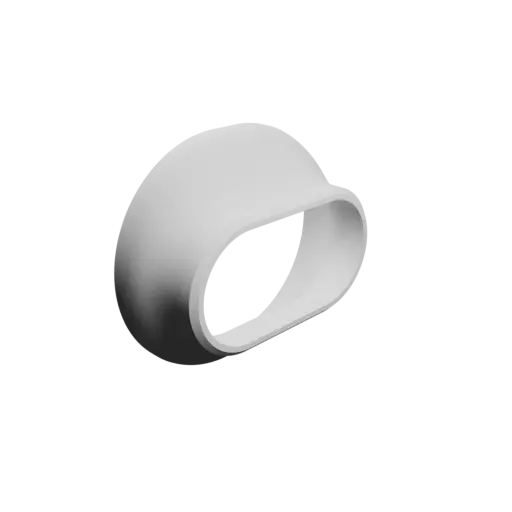
Oval connector available as a STL 3D file. The internal cross-section on side A is 91x80 mm, while on side B it is 80x40 mm. The useful sleeve length on side A is 5 mm, while on side B it reaches 10 mm. The transition section between the two ends is 20 mm long, for an overall length of 35 mm (sleeve A, transition and sleeve B). The shell is relatively thick, with a wall thickness of 4 mm. External chamfers are added at the ends to make it easier to insert the adapter into ducts or hoses.
| Parameter | Value | Unit |
|---|---|---|
| side A internal width | 91 | mm |
| side A internal height | 80 | mm |
| sleeve length on side A | 5 | mm |
| side B internal width | 80 | mm |
| side B internal height | 40 | mm |
| sleeve length on side B | 10 | mm |
| thickness | 4 | mm |
| transition length | 20 | mm |
| Y offset | 0 | mm |
| Z offset | 0 | mm |
| end chamfers | outside |
Oval duct transition fitting STL file 100x80 mm to 80x40 mm – transition: 20 mm (📦 #4451)
1 object(s) - format STL
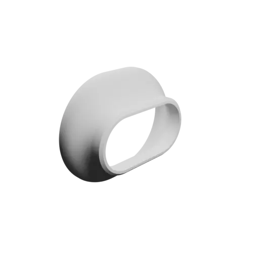
Oval pipe adapter provided as a STL 3D file. On side A, the internal cross-section is 100x80 mm, whereas on side B it is 80x40 mm. The sleeves also differ in useful length: 5 mm on side A and 10 mm on side B. Between the two sleeves, the transition runs over 20 mm, resulting in an overall length of 35 mm. With 4 mm of wall thickness, the adapter gains extra strength. External chamfers are added at the ends to make it easier to insert the adapter into ducts or hoses.
| Parameter | Value | Unit |
|---|---|---|
| side A internal width | 100 | mm |
| side A internal height | 80 | mm |
| sleeve length on side A | 5 | mm |
| side B internal width | 80 | mm |
| side B internal height | 40 | mm |
| sleeve length on side B | 10 | mm |
| thickness | 4 | mm |
| transition length | 20 | mm |
| Y offset | 0 | mm |
| Z offset | 0 | mm |
| end chamfers | outside |
Oval duct transition adapter STL file 80.1x80 mm to 80x40 mm – transition: 20 mm (📦 #4270)
1 object(s) - format STL
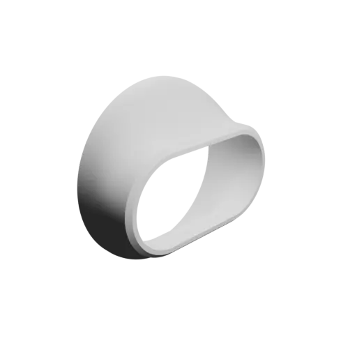
STL 3D file for an oval hose fitting. On side A, the internal cross-section is 80.1x80 mm (nearly circular), whereas on side B it is 80x40 mm (oval). The sleeve on side A provides a useful length of 5 mm, and on side B 10 mm. The transition section is 20 mm long, for a final overall length of 35 mm. The wall is on the thicker side at 4 mm. External chamfers at the ends help with engagement and assembly within the duct system.
| Parameter | Value | Unit |
|---|---|---|
| side A internal width | 80.1 | mm |
| side A internal height | 80 | mm |
| sleeve length on side A | 5 | mm |
| side B internal width | 80 | mm |
| side B internal height | 40 | mm |
| sleeve length on side B | 10 | mm |
| thickness | 4 | mm |
| transition length | 20 | mm |
| Y offset | 0 | mm |
| Z offset | 0 | mm |
| end chamfers | outside |
Oval duct transition fitting STL file 100.1x100 mm to 80x40 mm – transition: 20 mm (📦 #4342)
1 object(s) - format STL
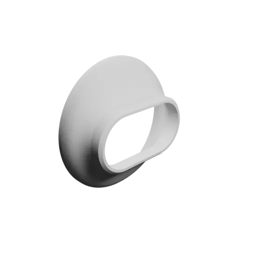
STL 3D file for an oval duct adapter. On side A, the internal cross-section is 100.1x100 mm (nearly circular), whereas on side B it is 80x40 mm (oval). You get a sleeve of 5 mm on side A and 10 mm on side B. The transition section is 20 mm long, for a final overall length of 35 mm. Wall thickness is generous (4 mm). External chamfers are added at the ends to make it easier to insert the adapter into ducts or hoses.
| Parameter | Value | Unit |
|---|---|---|
| side A internal width | 100.1 | mm |
| side A internal height | 100 | mm |
| sleeve length on side A | 5 | mm |
| side B internal width | 80 | mm |
| side B internal height | 40 | mm |
| sleeve length on side B | 10 | mm |
| thickness | 4 | mm |
| transition length | 20 | mm |
| Y offset | 0 | mm |
| Z offset | 0 | mm |
| end chamfers | outside |
Oval duct transition adapter STL file 100x70 mm to 80x40 mm – transition: 20 mm (📦 #4452)
1 object(s) - format STL
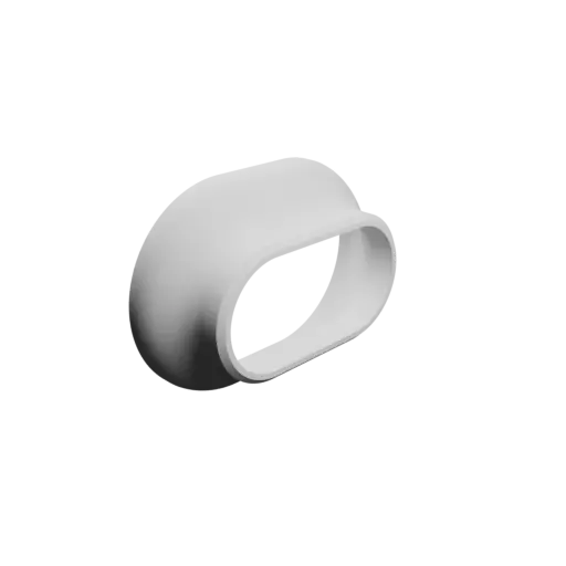
Oval pipe adapter provided as a STL 3D file. The internal cross-section on side A is 100x70 mm, while on side B it is 80x40 mm. You get a sleeve of 5 mm on side A and 10 mm on side B. The transition section is 20 mm long, for a final overall length of 35 mm. The shell is relatively thick, with a wall thickness of 4 mm. External chamfers are added at the ends to make it easier to insert the adapter into ducts or hoses.
| Parameter | Value | Unit |
|---|---|---|
| side A internal width | 100 | mm |
| side A internal height | 70 | mm |
| sleeve length on side A | 5 | mm |
| side B internal width | 80 | mm |
| side B internal height | 40 | mm |
| sleeve length on side B | 10 | mm |
| thickness | 4 | mm |
| transition length | 20 | mm |
| Y offset | 0 | mm |
| Z offset | 0 | mm |
| end chamfers | outside |
Oval duct transition fitting STL file 90x10 mm to 37.5x37.4 mm – transition: 50 mm (📦 #12277)
1 object(s) - format STL
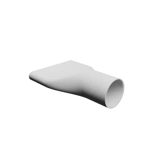
STL 3D file for an oval adapter. Side A offers an internal cross-section of 90x10 mm (oval) and side B 37.5x37.4 mm (nearly circular). Each sleeve provides a useful length of 40 mm. The transition section is 50 mm long, for a final overall length of 130 mm. The internal chamfers help start the duct insertion more easily.
| Parameter | Value | Unit |
|---|---|---|
| side A internal width | 90 | mm |
| side A internal height | 10 | mm |
| sleeve length on side A | 40 | mm |
| side B internal width | 37.5 | mm |
| side B internal height | 37.4 | mm |
| sleeve length on side B | 40 | mm |
| thickness | 2 | mm |
| transition length | 50 | mm |
| Y offset | 0 | mm |
| Z offset | 0 | mm |
| end chamfers | inside |
Oval duct transition adapter STL 3D file 63x47 mm to 53x37 mm – transition: 110 mm (📦 #10859)
1 object(s) - format STL
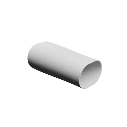
Oval adapter available as a STL 3D file. Side A offers an internal cross-section of 63x47 mm and side B 53x37 mm. Both sleeves share an identical useful length of 5 mm. Between the two sleeves, the transition runs over 110 mm, resulting in an overall length of 120 mm. The internal edges at the ends are chamfered to help guide the duct during insertion.
| Parameter | Value | Unit |
|---|---|---|
| side A internal width | 63 | mm |
| side A internal height | 47 | mm |
| sleeve length on side A | 5 | mm |
| side B internal width | 53 | mm |
| side B internal height | 37 | mm |
| sleeve length on side B | 5 | mm |
| thickness | 2 | mm |
| transition length | 110 | mm |
| Y offset | 0 | mm |
| Z offset | 0 | mm |
| end chamfers | inside |
Hose-shaped reducer STL file 152x50 mm to 76x75 mm – transition: 30 mm (📦 #11971)
1 object(s) - format STL
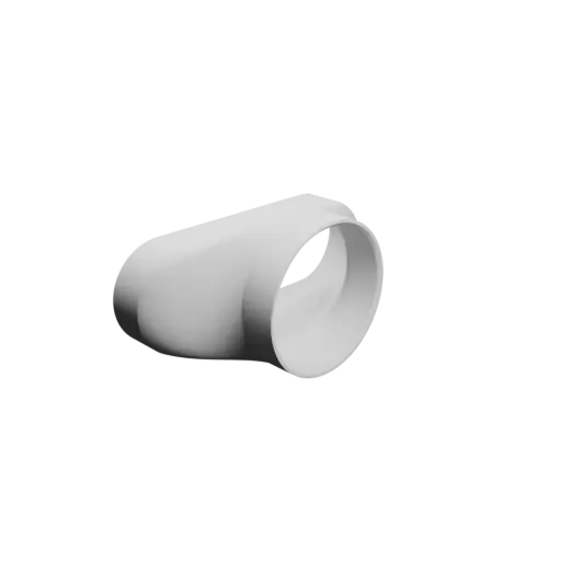
Oval hose fitting available as a STL 3D file. The internal cross-section on side A is 152x50 mm (oval), while on side B it is 76x75 mm (nearly circular). The sleeves on sides A and B have the same useful length of 20 mm. The central transition occupies 30 mm, bringing the overall length to 70 mm. The internal edges at the ends are chamfered to help guide the duct during insertion.
| Parameter | Value | Unit |
|---|---|---|
| side A internal width | 152 | mm |
| side A internal height | 50 | mm |
| sleeve length on side A | 20 | mm |
| side B internal width | 76 | mm |
| side B internal height | 75 | mm |
| sleeve length on side B | 20 | mm |
| thickness | 3 | mm |
| transition length | 30 | mm |
| Y offset | 0 | mm |
| Z offset | 0 | mm |
| end chamfers | inside |
Oval duct transition fitting STL file 120.1x120 mm to 80x40 mm – transition: 20 mm (📦 #4343)
1 object(s) - format STL
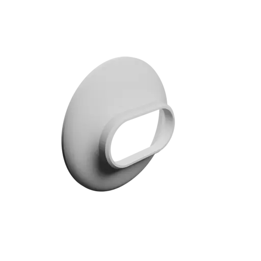
STL 3D file for an oval duct fitting. The internal cross-section on side A is 120.1x120 mm (nearly circular), while on side B it is 80x40 mm (oval). On side A, the sleeve is 5 mm long, and on side B 10 mm. The central transition occupies 20 mm, bringing the overall length to 35 mm. A thickness of 4 mm provides good stiffness. The external chamfers improve fit when inserting the adapter into ducts or hoses.
| Parameter | Value | Unit |
|---|---|---|
| side A internal width | 120.1 | mm |
| side A internal height | 120 | mm |
| sleeve length on side A | 5 | mm |
| side B internal width | 80 | mm |
| side B internal height | 40 | mm |
| sleeve length on side B | 10 | mm |
| thickness | 4 | mm |
| transition length | 20 | mm |
| Y offset | 0 | mm |
| Z offset | 0 | mm |
| end chamfers | outside |
Oval hose adapter STL file 36.1x32.9 mm to 31.6x31.5 mm – transition: 20 mm (📦 #4829)
1 object(s) - format STL
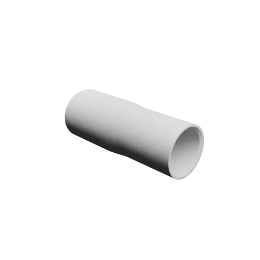
Oval hose adapter available as a STL 3D file. The internal cross-section on side A is 36.1x32.9 mm (oval), while on side B it is 31.6x31.5 mm (nearly circular). Both sleeves share an identical useful length of 42 mm. The transition section is 20 mm long, for a final overall length of 104 mm. The internal edges at the ends are chamfered to help guide the duct during insertion.
| Parameter | Value | Unit |
|---|---|---|
| side A internal width | 36.1 | mm |
| side A internal height | 32.9 | mm |
| sleeve length on side A | 42 | mm |
| side B internal width | 31.6 | mm |
| side B internal height | 31.5 | mm |
| sleeve length on side B | 42 | mm |
| thickness | 3 | mm |
| transition length | 20 | mm |
| Y offset | 0 | mm |
| Z offset | 0 | mm |
| end chamfers | inside |
Oval duct transition fitting STL file 50x20 mm to 35.6x35.5 mm – transition: 20 mm (📦 #9780)
1 object(s) - format STL
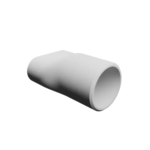
Oval duct adapter provided as a STL 3D file. Side A offers an internal cross-section of 50x20 mm (oval) and side B 35.6x35.5 mm (nearly circular). On side A, the sleeve is 20 mm long, and on side B 35 mm. The transition section between the two ends is 20 mm long, for an overall length of 75 mm (sleeve A, transition and sleeve B). The external chamfers improve fit when inserting the adapter into ducts or hoses.
| Parameter | Value | Unit |
|---|---|---|
| side A internal width | 50 | mm |
| side A internal height | 20 | mm |
| sleeve length on side A | 20 | mm |
| side B internal width | 35.6 | mm |
| side B internal height | 35.5 | mm |
| sleeve length on side B | 35 | mm |
| thickness | 3 | mm |
| transition length | 20 | mm |
| Y offset | 0 | mm |
| Z offset | 0 | mm |
| end chamfers | outside |
Hose-shaped reducer STL 3D file 140x80 mm to 130x35 mm – transition: 40 mm (📦 #4346)
1 object(s) - format STL
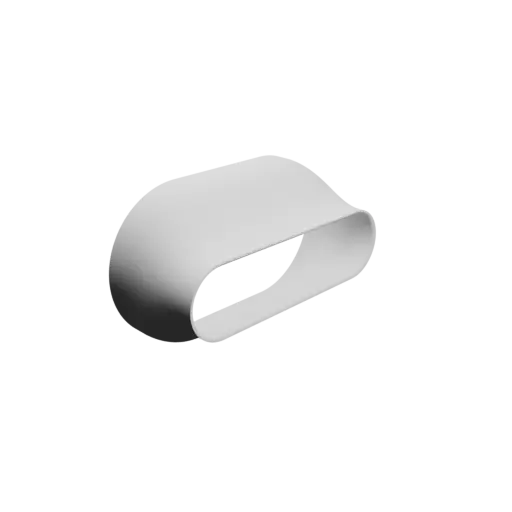
STL 3D file for an oval hose fitting. The internal cross-section on side A is 140x80 mm, while on side B it is 130x35 mm. You get a sleeve of 8 mm on side A and 6 mm on side B. The transition links the two ends over 40 mm, with a total overall length of 54 mm. Internal chamfers at the ends improve assembly and make insertion smoother.
| Parameter | Value | Unit |
|---|---|---|
| side A internal width | 140 | mm |
| side A internal height | 80 | mm |
| sleeve length on side A | 8 | mm |
| side B internal width | 130 | mm |
| side B internal height | 35 | mm |
| sleeve length on side B | 6 | mm |
| thickness | 2 | mm |
| transition length | 40 | mm |
| Y offset | 0 | mm |
| Z offset | 0 | mm |
| end chamfers | inside |
Oval duct transition adapter STL 3D file 160x37 mm to 45.1x45 mm – transition: 20 mm (📦 #5211)
1 object(s) - format STL
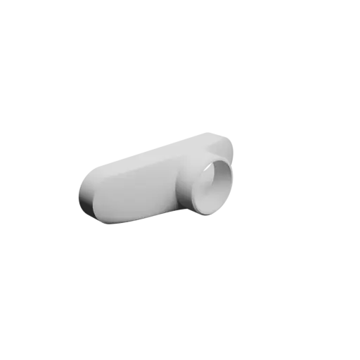
STL 3D file for an oval duct adapter. The internal cross-section on side A is 160x37 mm (oval), while on side B it is 45.1x45 mm (nearly circular). The useful length is consistent on both ends: 20 mm. The transition links the two ends over 20 mm, with a total overall length of 60 mm. External chamfers at the ends help with engagement and assembly within the duct system. Side B is offset by 10 mm along the Y axis relative to side A.
| Parameter | Value | Unit |
|---|---|---|
| side A internal width | 160 | mm |
| side A internal height | 37 | mm |
| sleeve length on side A | 20 | mm |
| side B internal width | 45.1 | mm |
| side B internal height | 45 | mm |
| sleeve length on side B | 20 | mm |
| thickness | 3 | mm |
| transition length | 20 | mm |
| Y offset | 10 | mm |
| Z offset | 0 | mm |
| end chamfers | outside |
Oval hose adapter STL 3D file 53x52 mm to 50x28 mm – transition: 20 mm (📦 #4337)
1 object(s) - format STL
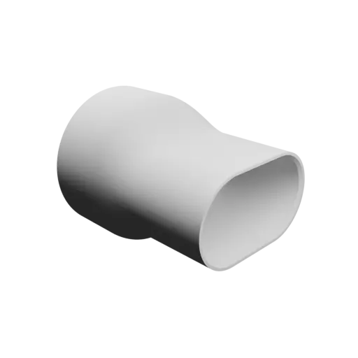
Oval connector available as a STL 3D file. The internal cross-section on side A is 53x52 mm (nearly circular), while on side B it is 50x28 mm (oval). On side A, the sleeve is 20 mm long, and on side B 30 mm. The transition section is 20 mm long, for a final overall length of 70 mm. The internal edges at the ends are chamfered to help guide the duct during insertion.
| Parameter | Value | Unit |
|---|---|---|
| side A internal width | 53 | mm |
| side A internal height | 52 | mm |
| sleeve length on side A | 20 | mm |
| side B internal width | 50 | mm |
| side B internal height | 28 | mm |
| sleeve length on side B | 30 | mm |
| thickness | 2 | mm |
| transition length | 20 | mm |
| Y offset | 0 | mm |
| Z offset | 0 | mm |
| end chamfers | inside |
Oval hose adapter STL file 121x120.5 mm to 90x53 mm – transition: 63 mm (📦 #9581)
1 object(s) - format STL
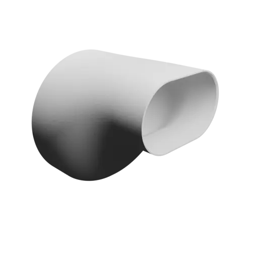
Oval coupling in STL 3D file format. On side A, the internal cross-section is 121x120.5 mm (nearly circular), whereas on side B it is 90x53 mm (oval). The sleeve on side A provides a useful length of 25 mm, and on side B 30 mm. The transition section is 63 mm long, for a final overall length of 118 mm. Internal chamfers at the ends improve assembly and make insertion smoother. An offset of 31.5 mm along the Z axis is applied to side B relative to side A.
| Parameter | Value | Unit |
|---|---|---|
| side A internal width | 121 | mm |
| side A internal height | 120.5 | mm |
| sleeve length on side A | 25 | mm |
| side B internal width | 90 | mm |
| side B internal height | 53 | mm |
| sleeve length on side B | 30 | mm |
| thickness | 2 | mm |
| transition length | 63 | mm |
| Y offset | 0 | mm |
| Z offset | 31.5 | mm |
| end chamfers | inside |
Oval hose adapter STL 3D file 140x50 mm to 130x35 mm – transition: 40 mm (📦 #4345)
1 object(s) - format STL
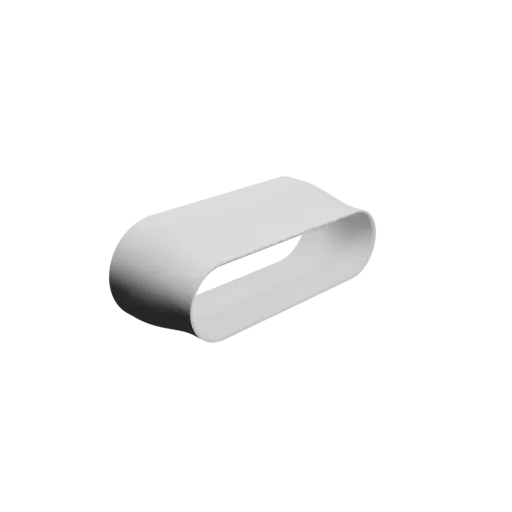
Oval connector available as a STL 3D file. On side A, the internal cross-section is 140x50 mm, whereas on side B it is 130x35 mm. You get a sleeve of 8 mm on side A and 6 mm on side B. The central transition occupies 40 mm, bringing the overall length to 54 mm. The internal chamfers help start the duct insertion more easily.
| Parameter | Value | Unit |
|---|---|---|
| side A internal width | 140 | mm |
| side A internal height | 50 | mm |
| sleeve length on side A | 8 | mm |
| side B internal width | 130 | mm |
| side B internal height | 35 | mm |
| sleeve length on side B | 6 | mm |
| thickness | 2 | mm |
| transition length | 40 | mm |
| Y offset | 0 | mm |
| Z offset | 0 | mm |
| end chamfers | inside |
Oval duct transition fitting STL file 30x10 mm to 40x10 mm – transition: 100 mm (📦 #11928)
1 object(s) - format STL
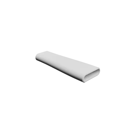
STL 3D file for an oval hose adapter. Side A offers an internal cross-section of 30x10 mm and side B 40x10 mm. Each sleeve provides a useful length of 10 mm. The transition section between the two ends is 100 mm long, for an overall length of 120 mm (sleeve A, transition and sleeve B). External chamfers are added at the ends to make it easier to insert the adapter into ducts or hoses.
| Parameter | Value | Unit |
|---|---|---|
| side A internal width | 30 | mm |
| side A internal height | 10 | mm |
| sleeve length on side A | 10 | mm |
| side B internal width | 40 | mm |
| side B internal height | 10 | mm |
| sleeve length on side B | 10 | mm |
| thickness | 2 | mm |
| transition length | 100 | mm |
| Y offset | 0 | mm |
| Z offset | 0 | mm |
| end chamfers | outside |
Oval hose adapter STL 3D file 140x40 mm to 130x35 mm – transition: 40 mm (📦 #4268)
1 object(s) - format STL
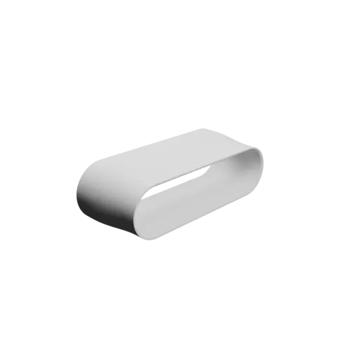
Oval connector available as a STL 3D file. On side A, the internal cross-section is 140x40 mm, whereas on side B it is 130x35 mm. The useful sleeve length on side A is 8 mm, while on side B it reaches 6 mm. The transition section between the two ends is 40 mm long, for an overall length of 54 mm (sleeve A, transition and sleeve B). The internal edges at the ends are chamfered to help guide the duct during insertion.
| Parameter | Value | Unit |
|---|---|---|
| side A internal width | 140 | mm |
| side A internal height | 40 | mm |
| sleeve length on side A | 8 | mm |
| side B internal width | 130 | mm |
| side B internal height | 35 | mm |
| sleeve length on side B | 6 | mm |
| thickness | 2 | mm |
| transition length | 40 | mm |
| Y offset | 0 | mm |
| Z offset | 0 | mm |
| end chamfers | inside |
Oval duct transition adapter STL file 43x35 mm to 58.1x58 mm – transition: 20 mm (📦 #5388)
1 object(s) - format STL
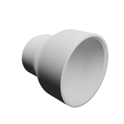
Oval coupling in STL 3D file format. Side A offers an internal cross-section of 43x35 mm (oval) and side B 58.1x58 mm (nearly circular). The useful lengths are 18 mm (A) and 25 mm (B), respectively. The transition section is 20 mm long, for a final overall length of 63 mm. The wall is on the thicker side at 4 mm. The internal chamfers help start the duct insertion more easily.
| Parameter | Value | Unit |
|---|---|---|
| side A internal width | 43 | mm |
| side A internal height | 35 | mm |
| sleeve length on side A | 18 | mm |
| side B internal width | 58.1 | mm |
| side B internal height | 58 | mm |
| sleeve length on side B | 25 | mm |
| thickness | 4 | mm |
| transition length | 20 | mm |
| Y offset | 0 | mm |
| Z offset | 0 | mm |
| end chamfers | inside |
Oval hose adapter STL 3D file 150x40 mm to 130x35 mm – transition: 40 mm (📦 #4453)
1 object(s) - format STL
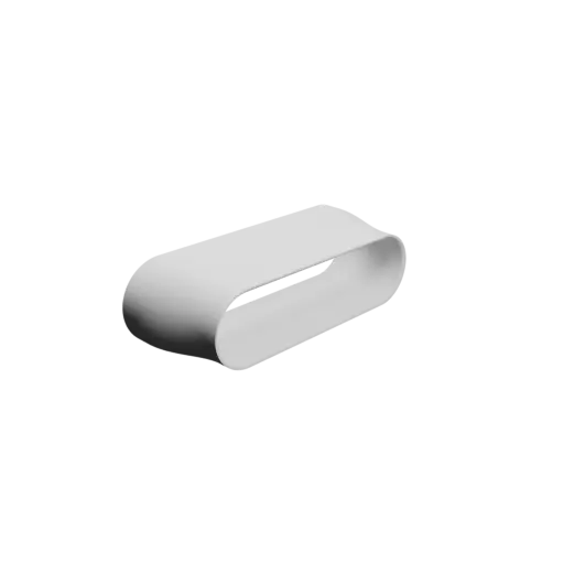
Oval duct transition adapter in STL 3D file format. Side A offers an internal cross-section of 150x40 mm and side B 130x35 mm. The sleeve on side A provides a useful length of 8 mm, and on side B 6 mm. Between the two sleeves, the transition runs over 40 mm, resulting in an overall length of 54 mm. Internal chamfers at the ends improve assembly and make insertion smoother.
| Parameter | Value | Unit |
|---|---|---|
| side A internal width | 150 | mm |
| side A internal height | 40 | mm |
| sleeve length on side A | 8 | mm |
| side B internal width | 130 | mm |
| side B internal height | 35 | mm |
| sleeve length on side B | 6 | mm |
| thickness | 2 | mm |
| transition length | 40 | mm |
| Y offset | 0 | mm |
| Z offset | 0 | mm |
| end chamfers | inside |
Oval hose adapter STL 3D file 36.1x32.9 mm to 28.5x28.4 mm – transition: 20 mm (📦 #4833)
1 object(s) - format STL
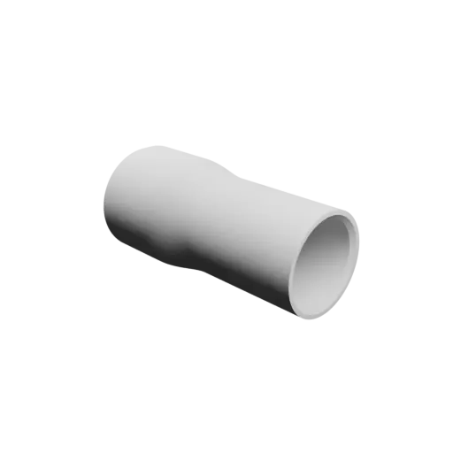
Oval duct transition adapter available as a STL 3D file. The internal cross-section on side A is 36.1x32.9 mm (oval), while on side B it is 28.5x28.4 mm (nearly circular). The useful lengths are 22 mm (A) and 42 mm (B), respectively. The central transition occupies 20 mm, bringing the overall length to 84 mm. The internal edges at the ends are chamfered to help guide the duct during insertion.
| Parameter | Value | Unit |
|---|---|---|
| side A internal width | 36.1 | mm |
| side A internal height | 32.9 | mm |
| sleeve length on side A | 22 | mm |
| side B internal width | 28.5 | mm |
| side B internal height | 28.4 | mm |
| sleeve length on side B | 42 | mm |
| thickness | 3 | mm |
| transition length | 20 | mm |
| Y offset | 0 | mm |
| Z offset | 0 | mm |
| end chamfers | inside |