Why Modeling Strategy Matters in Procedural CAD Modeling
Why does modeling strategy matter so much in procedural CAD? Two scripts can produce the exact same geometry while showing very different generation times.
Using a concrete build123d example, this article explains why certain operations, such as fillets, become expensive when repeated at scale, and how a simple change in approach can drastically reduce computation time.
A clear overview of the key challenges in procedural modeling, highlighting the direct impact of design choices on CAD engine performance.
What are we talking about?
Anyone who has ever written code—whether as a hobby or professionally—knows that there are often, if not always, multiple ways to achieve the same result.
To take a deliberately simple example, the number 2 can be obtained
using 1 + 1, but also with 12 / (4 + 2).
There is no doubt that 1 + 1 is more efficient:
it is easier to read, faster to understand,
and it requires fewer operations,
both for us as humans
and for the machine executing the code.
If you enter both calculations into your calculator or your computer,
you will get the same result, instantly from your point of view.
But under the hood, it is not the same story:
the second method requires more, essentially “unnecessary,” computations for the machine.
Procedural 3D modeling is obviously a completely different matter, far more complex than these simple calculations. As a result, the modeling strategy—that is, how you program the model generation— has a direct impact on performance, and therefore on the generation time. That is exactly what we are going to examine here.
Some operations are more expensive than others
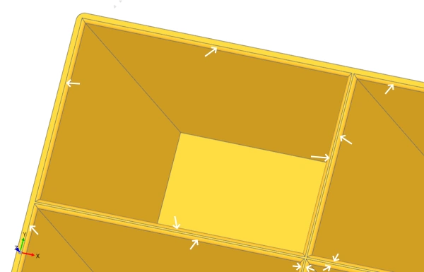
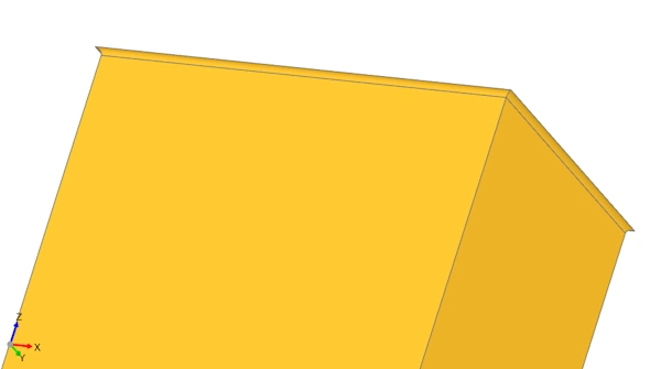
To address this issue, we will rely on the template for generating a storage organizer with drawers. In addition to drawers and optional dividers, this template generates, as its main component, a block made up of cavities whose count is configurable through the number of columns and rows. To make inserting and removing the drawers easier, the cavities feature rounded edges (fillets). The base script can look like this:
from build123d import *
from ocp_vscode import show
import time

ROWS = 20
COLS = 20

CAVITY_W = 60
CAVITY_H = 40
CAVITY_D = 100

WALL = 2
FILLET = 0.8
RADIUS = 1.8
TOL = 1e-3

# --------------------------
# Derived dimensions
# --------------------------
BLOCK_W = COLS * CAVITY_W + (COLS + 1) * WALL
BLOCK_H = ROWS * CAVITY_H + (ROWS + 1) * WALL
BLOCK_D = WALL + CAVITY_D

PITCH_X = CAVITY_W + WALL
PITCH_Y = CAVITY_H + WALL
CUT_D   = BLOCK_D - WALL

t0 = time.perf_counter()

# --------------------------
# Geometry
# --------------------------
with BuildPart() as bp:
    # main block
    with BuildSketch(Plane.XY):
        RectangleRounded(BLOCK_W, BLOCK_H, radius=RADIUS)
    extrude(amount=BLOCK_D)

    # subtract grid of cavities (20x20 = 400)
    with BuildSketch(Plane.XY.offset(WALL)):
        with GridLocations(
            x_spacing=PITCH_X,
            y_spacing=PITCH_Y,
            x_count=COLS,
            y_count=ROWS
        ):
            Rectangle(CAVITY_W, CAVITY_H)
    extrude(amount=CUT_D, mode=Mode.SUBTRACT)

    # fillet only top opening edges
    top_edges = [e for e in bp.edges() if abs(e.center().Z - BLOCK_D) <= TOL]

    def is_x_edge(e: Edge) -> bool:
        v1, v2 = [v.position for v in e.vertices()]
        return abs(v1.Y - v2.Y) <= TOL

    def is_y_edge(e: Edge) -> bool:
        v1, v2 = [v.position for v in e.vertices()]
        return abs(v1.X - v2.X) <= TOL

    edges = (
        [e for e in top_edges if is_x_edge(e) and abs(e.length - CAVITY_W) <= TOL] +
        [e for e in top_edges if is_y_edge(e) and abs(e.length - CAVITY_H) <= TOL]
    )

    if edges:
        fillet(edges, radius=FILLET)

block = bp.part

t1 = time.perf_counter()

print(f"Build time: {t1 - t0:.2f} s")
print(f"Cavities: {ROWS * COLS}")

show(block)
This approach is fairly “linear.” You create a block, subtract cavities, then select all the edges and apply a fillet. Executing this script takes a few seconds for a handful of cavities. But when generating 400 compartments (20 rows × 20 columns), the same script can take more than an hour.
Why? Generating fillets is a heavy, computationally expensive operation, because it relies on complex geometric calculations performed on geometry that already exists. Unlike a simple extrusion or cut, a fillet forces the CAD engine to analyze existing edges, locally rebuild adjacent surfaces, and then recompute intersections and geometric continuity across all affected faces.
Changing your modeling strategy
The script shown above works in the sense that it does produce the requested 3D geometry. However, its execution time is extremely long due to the repeated use of operations that are expensive in terms of computation, and therefore time.
We will see that it is possible to obtain the exact same geometry much more efficiently by changing strategy.
Jern on the build123d Discord suggests another, far more efficient approach. The idea is to create a tool that already contains the imprint of the fillets, and to use this tool to create the cavities. The gain is massive: the geometry is generated in just a few seconds.
from build123d import *
from ocp_vscode import show
import time

# --------------------------
# Minimal fixed geometry
# --------------------------
ROWS = 20
COLS = 20

CAVITY_W = 60
CAVITY_H = 40
CAVITY_D = 100

WALL = 2
RADIUS = 1.8
OPENING_FILLET = 0.8

# --------------------------
# Derived dimensions
# --------------------------
BLOCK_W = COLS * CAVITY_W + (COLS + 1) * WALL
BLOCK_H = ROWS * CAVITY_H + (ROWS + 1) * WALL
BLOCK_D = WALL + CAVITY_D

PITCH_X = CAVITY_W + WALL
PITCH_Y = CAVITY_H + WALL
CUT_D   = BLOCK_D - WALL

t0 = time.perf_counter()

# --------------------------
# Main block
# --------------------------
with BuildPart() as bp:
    # EN: Main solid block
    with BuildSketch(Plane.XY):
        RectangleRounded(BLOCK_W, BLOCK_H, radius=RADIUS)
    extrude(amount=BLOCK_D)

# --------------------------
# Single cavity "tool" with built-in top fillet/flare
# (this tool will later be patterned with GridLocations)
# --------------------------
with BuildPart() as p2:
    # EN: Base cavity prism (starts at Z=WALL)
    with BuildSketch(Plane.XY.offset(WALL)):
        Rectangle(CAVITY_W, CAVITY_H)
    extrude(amount=CUT_D)

    # EN: Grab current top face of the cavity prism
    top_face = p2.faces().sort_by(Axis.Z)[-1]

    # EN: Create a small "cap" by offsetting the top face (to create space for fillet)
    with BuildSketch(top_face):
        add(top_face)
        offset(amount=2)
    extrude(amount=1)

    # EN: Apply fillet on the original top face edges (fast on a single cavity tool)
    fillet(top_face.edges(), OPENING_FILLET)

    # EN: Remove the non-fillet extra cap to avoid overlaps when patterning
    new_top_face = p2.faces().sort_by(Axis.Z)[-1]
    with BuildSketch(new_top_face):
        add(new_top_face)
    extrude(amount=-1, mode=Mode.SUBTRACT)

# --------------------------
# Pattern the cavity tool and subtract in algebra mode
# --------------------------
tool = GridLocations(
    x_spacing=PITCH_X,
    y_spacing=PITCH_Y,
    x_count=COLS,
    y_count=ROWS
) * p2.part

block = bp.part - tool

t1 = time.perf_counter()

print(f"Build time: {t1 - t0:.2f} s")
print(f"Cavities: {ROWS * COLS}")

# --------------------------
# Show
# --------------------------
show(block)
Why is this version so much more efficient? The second strategy is not faster because it creates fewer cavities, but because it avoids applying a fillet to 1,600 edges (4 × 400) on a solid that becomes increasingly complex. Instead, this approach computes the 4 fillets on a simple shape, only once, and then performs 400 boolean subtraction operations using an already-rounded shape.
This demonstration highlights the fact that programmatic modeling is not just a sequence of operations. The code in the second strategy is not more complex; it is more intelligent, because it takes into account the internal mechanics of the CAD engine.