Modify 3D geometry in the slicer
Editing 3D geometry without CAD software is absolutely possible!
In this article, you’ll learn how to tweak your models directly in your slicer. It’s the perfect approach when the generated model is almost right but still needs a small adjustment.
You’ll see how to rescale a part, work axis by axis, and even compensate for a missing step size in the template, with concrete examples like the honeycomb grid and snap-on pipe clip holders.
We’ll also look at the slicer’s advanced editing tools: adding volumes, subtracting geometry, embossed or debossed text, and custom holes — all simple operations that let you adapt an existing STL with zero CAD skills.
A practical, quick, and handy guide to personalize your prints in just a few clicks!
Why do this?
The very essence of iteration3d is to generate custom 3D geometries. The number of parameters available in the templates is intentionally limited for interface usability. Likewise, the adjustment steps for these parameters vary in range.
It is therefore possible to end up in a situation where the generated model almost perfectly matches the need, with only one or two minor adjustments missing. In this article, we will see how it is possible to modify the geometry directly in the object slicer, or slicer. The screenshots shown in this article come from PrusaSlicer.
Adjusting the scale
The most accessible geometry modification is scale adjustment. Slicers allow homothetic scaling (which affects all axes with the same value) as well as axis-by-axis scaling: X, Y, and Z.
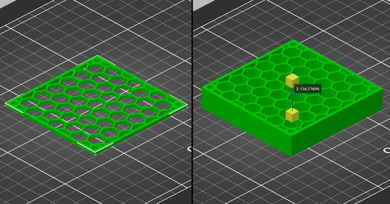
Taking the example of the honeycomb grid STL generator, this adjustment is entirely possible and even recommended. This template intentionally generates grids with a constant 2 mm thickness. The user is then free to increase or decrease this thickness by adjusting the scale on Z. This action will not modify any other part of the model. Length, width, and cell size will remain identical.
Let’s continue with scale adjustment with the snap-in tube holders. In this template, the tube diameter step is 1 mm. It is not possible to request a clip for a tube diameter of 80.5 mm, for example. While this 1 mm step should cover the vast majority of needs, you may want to reduce this diameter by 0.5 mm to better match your application. In this case, you can choose to slightly adjust the scale on X and Y. But be careful: this will also modify the screw hole, which will change as well. However, the modification of the hole diameter is generally tolerable and negligible compared to the improvement obtained on the tube diameter.
We have now seen that scale adjustment makes it possible to modify a geometry in a fully controlled way in the case of the honeycomb grid, or to adapt the geometry while tolerating some imprecision in the case of the tube clip.
Adding or subtracting a volume
PrusaSlicer includes a very interesting feature accessible via a simple right-click on the object: add part and add negative volume. Each of these two options makes it possible to add a wide variety of shapes: box, cylinder, text, etc., and even load an external volume from your desktop. Once the new volume is positioned, it becomes an integral part of the geometry in additive or subtractive mode.
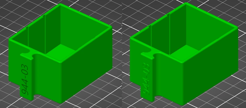
Let’s begin with additive mode. We’ll take the template organizer with compartments. We will modify a drawer by adding text on the handle. Simply select “Add shape” > “Text”. By applying a rotation to this new object and positioning it correctly, it is possible to add a code in the form of text on the handle. Very practical and very easy!
With the “Add part” option you will obtain an embossed effect, and with the “Add negative volume” option you will obtain a debossed effect. Be careful to limit internal or external offset to 0.10 to 0.30 mm maximum so that the print proceeds correctly without supports.
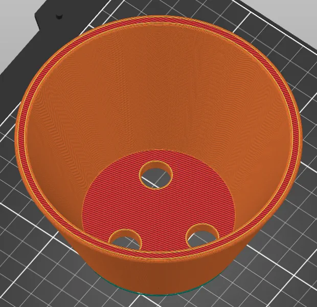
Another example with the template that generates 3D pots. The template generates pots or bowls with a solid bottom. We will add openings to turn this basic pot into a flower pot. As you’ve understood, you simply need to add as many negative “cylinder” volumes to the bottom of the pot as the number of holes you want.
These are a few small tips that allow you to adapt an existing 3D design quickly. You will notice that the dimensions and placement of these new shapes are not extremely precise. But they make it possible to easily solve a specific problem.