What is the STL 3D file format ?
Do you often use STL files without really knowing what's inside them? This iconic format of 3D printing has existed since 1987… yet it still remains the undisputed standard today.
Discover the origin of the format, how it works based on a triangle mesh, and why it's so universally adopted.
Did you know that a simple fillet can multiply a file's size by 400? Or that just a few lines of text can generate a perfect cube?
Finally, understand its limitations… and why, despite them, it still dominates over newer formats. A complete, illustrated, and accessible article.
The origin of the STL format
The 3D file format STL was created in 1987 by the company 3D Systems, still a major player in 3D printing today. At the time, the company needed to define an exchange format for its 3D printing technology called "stereolithography," now better known as resin 3D printing.
And this is where the acronym "STL" originates — this sequence of three letters is in fact an abbreviation for "STereoLithography". You’ll also find another interpretation of "STL" as "Standard Triangle Language", which makes a lot of sense, as we’ll see later...
Back then, 3D Systems needed a file format that could meet the technical constraints of the very first commercial resin 3D printer. Computers were weak, and memory was scarce. They needed a file format as light and simple as possible, capable of describing only the external shape of an object without overloading the machine. That’s how STL was born — a minimalist format, defining the 3D model’s surface without textures or colors. A 3D shape defined as simply as possible for the time.
Although newer and richer formats for 3D printing have been developed recently (like the 3MF format), STL remains widely used today, both for resin 3D printing and fused filament fabrication (also known as "FFF" 3D printing).
What characterizes the STL 3D format?
An STL file describes a 3D shape. This shape is actually a mesh of triangles. When you view an STL file in a slicer, you’re actually seeing a shape composed of a juxtaposition of triangles. Surprising at first glance!
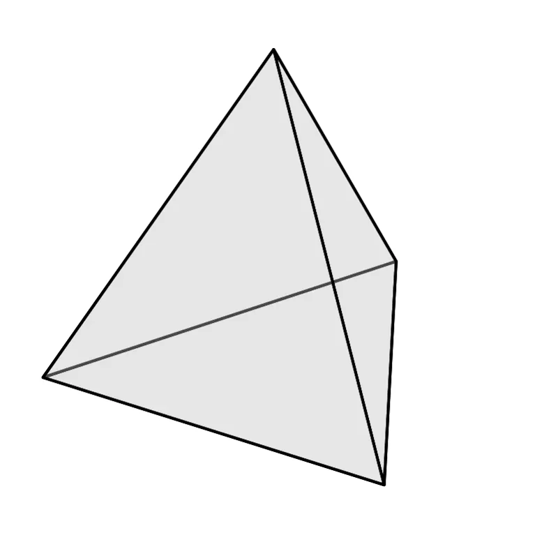
For instance, a rectangular prism (like a box-shaped object) is made up of 12 triangles — 2 triangles per face. So what’s the simplest 3D volume defined in STL? A tetrahedron, made of 4 triangles.
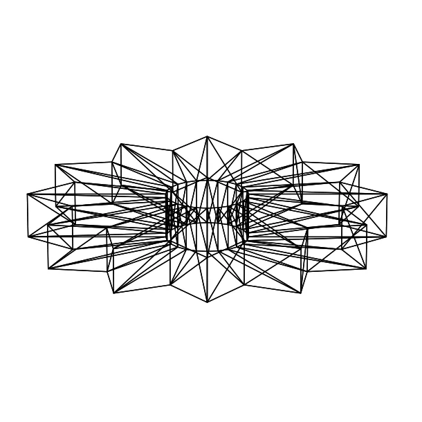
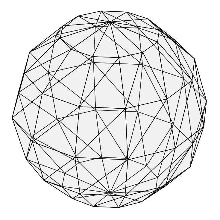
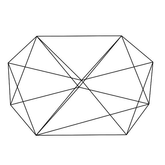
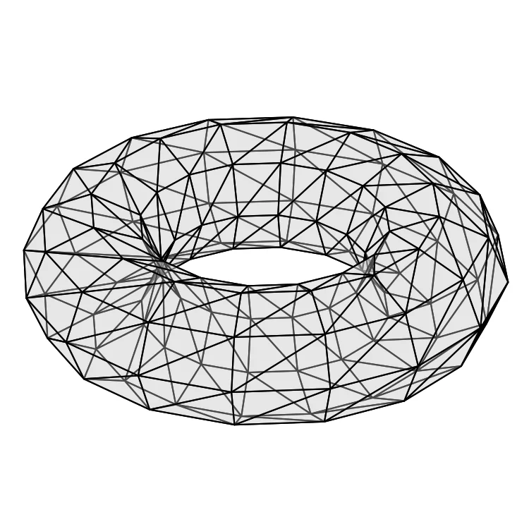
Here are some illustrative images showing visible triangles:
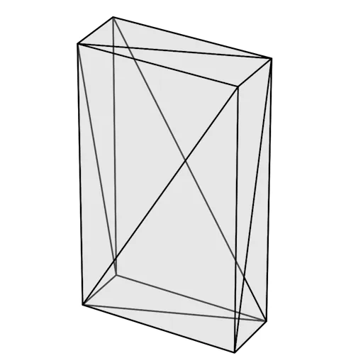
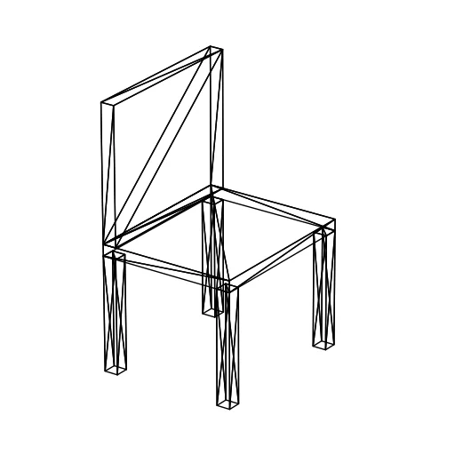
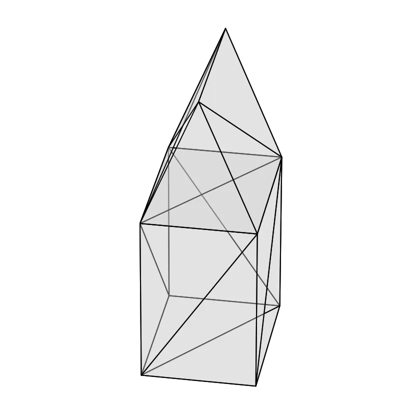
If you’ve worked with SketchUp or another CAD software solution, you’ve probably noticed this kind of triangle-based structure. Now you know why! So why is a triangle used as the base shape for any 3D volume? There are several reasons:
- Three points always define a plane, unlike four points, for example. (Real-life side note: a 3-legged stool will always have all its feet touching the floor. It will always be stable, unlike a 4-legged stool which might wobble because all its legs aren’t necessarily on the same plane!).
- A triangle is "simple" to handle for algorithms.
- If a complex surface has errors due to poor triangulation, it will still result in a simplified but usable output.
A 3D file is therefore a mesh of triangles, whether it's a cube or a sphere. For a pure cube, the number of triangles is fixed: 2 triangles per face × 6 faces = 12 triangles. For a sphere, it depends on the desired resolution. The smoother the sphere, the more triangles are needed, and the larger the file size.
As you can guess, "angular" shapes result in lighter files than spherical shapes. Let’s take an example from the 3D models available on iteration3d, specifically a cube measuring 100×100×100 mm. The STL file of model 745, a pure cube of 100×100×100 mm, weighs 1 KB. Add a 2 mm fillet (rounded edge) on all sides: model 744 weighs 462 KB! Rounded edges require a huge number of triangles, which translates to a much larger file.
What happens if you compare a 100×100×100 mm cube to one measuring 10×10×10 mm? Is it heavier? No — regardless of the cube’s size, the number of triangles remains the same (12), and so does the file size!
It’s the number of triangles that determines the file size. Take a tiny o-ring with an outer diameter of 10.1 mm and thickness of 2.4 mm, and it weighs 1550 KB! Of course, all these comparisons assume the same resolution definition.
What exactly does an STL file contain?
So, a 3D STL file is a triangle mesh. But how does this actually look? Well, as expected, an STL file defines... triangles. The code below defines a cube:
        solid cube
        facet normal 0 0 -1
            outer loop
            vertex 0 0 0
            vertex 100 0 0
            vertex 100 100 0
            endloop
        endfacet
        facet normal 0 0 -1
            outer loop
            vertex 0 0 0
            vertex 100 100 0
            vertex 0 100 0
            endloop
        endfacet

        facet normal 0 0 1
            outer loop
            vertex 0 0 100
            vertex 100 100 100
            vertex 100 0 100
            endloop
        endfacet
        facet normal 0 0 1
            outer loop
            vertex 0 0 100
            vertex 0 100 100
            vertex 100 100 100
            endloop
        endfacet

        facet normal 0 -1 0
            outer loop
            vertex 0 0 0
            vertex 100 0 100
            vertex 100 0 0
            endloop
        endfacet
        facet normal 0 -1 0
            outer loop
            vertex 0 0 0
            vertex 0 0 100
            vertex 100 0 100
            endloop
        endfacet

        facet normal 0 1 0
            outer loop
            vertex 0 100 0
            vertex 100 100 0
            vertex 100 100 100
            endloop
        endfacet
        facet normal 0 1 0
            outer loop
            vertex 0 100 0
            vertex 100 100 100
            vertex 0 100 100
            endloop
        endfacet

        facet normal -1 0 0
            outer loop
            vertex 0 0 0
            vertex 0 100 100
            vertex 0 0 100
            endloop
        endfacet
        facet normal -1 0 0
            outer loop
            vertex 0 0 0
            vertex 0 100 0
            vertex 0 100 100
            endloop
        endfacet

        facet normal 1 0 0
            outer loop
            vertex 100 0 0
            vertex 100 0 100
            vertex 100 100 100
            endloop
        endfacet
        facet normal 1 0 0
            outer loop
            vertex 100 0 0
            vertex 100 100 100
            vertex 100 100 0
            endloop
        endfacet
        endsolid cube
Copy this code and paste it into Notepad, for example. Save it as "test.stl". Open this STL in a slicer like PrusaSlicer, for example. What do you get? A 100×100×100 mm cube!
Let’s break down these few lines of code:
solid and endsolid define the model. Here, the name used is "cube", but it has no impact on the model generation. You could have used "model1" instead of "cube."
Each facet defines a triangle. So there are 12 of them in the case of a cube. These facets are grouped in pairs, representing the 6 faces of the cube.
Note that you just created an STL file in ASCII format. STL files are often available in binary format as it is less storage-intensive. These binary files, even when opened in an editor like Notepad, are not "readable" by a human, unlike ASCII files.
If you’d like to explore further, you can read this Wikipedia article.
Can an STL file be modified?
The first "modification" of an STL file consists of scaling it along one or more of its X, Y, or Z axes. You've probably already done this in your slicing software. This isn’t really a true modification. No triangles are removed or added — it’s simply changing the "proportions" of the mesh.
It is possible to reduce the number of triangles. This is referred to as polylow mode, short for low polygon. This doesn't apply to all models. Reducing the triangle count of a tetrahedron is impossible, and for some models, it would make no sense. This lowpoly transformation is useful for organic shapes. Reducing the triangle mesh can also help reduce the file size for quick previews of the object.
Other modifications are also possible, such as merging with other volumes, deformation, mirroring, etc. If you want to explore this further, you can check out software like Meshlab. Note that this tool can also repair STL files. It’s quite common to have to clean up an STL file due to open surfaces in the model, reversed faces, or open edges.
Some software tools can subdivide a triangle into multiple sub-triangles. By adjusting the coordinates of these new triangles, it becomes possible to create a new volume previously defined by just one triangle. This technique is often used to "smooth" a surface. This is known as highpoly mode.
STL: the ideal format?
The STL format is lightweight and simple. This likely explains its widespread use and compatibility. But this simplicity also brings limitations. An STL file contains no color or texture. It also doesn’t define units explicitly (as seen in the code above).
Another limitation: no matter how high the resolution is, this format doesn’t allow the definition of true mathematically smooth curves. Every curve is really just a section made up of many small triangles.
To overcome these limitations, a newer format called 3MF has been developed. Although this format is promoted by 3D printer manufacturers and its advantages are real, the STL format is still widely used today.
And then what?
Most 3D printers do not directly accept STL files. For the printer to be able to print the model, the STL file must be converted into a path for the print head. This is the role of slicing software, which usually converts the STL file into G-code. The G-code file contains movement instructions (as well as commands to heat the nozzle and the print bed).
Now you know just about everything there is to know about the STL file format!